


MATLAB INTRODUCTION:
Matlab is a program for doing numerical computation. It was
originally designed for solving linear algebra type problems using matrices.
Its name is derived from MATrix LABoratory.Matlab is also a programming
language that currently is widely used as a platform for developing tools for
Machine Learning.
Why it is useful for prototyping AI projects??
·
Large toolbox of numeric/image library
functions.
·
Very useful for displaying, visualizing
data.
·
High-level: focus on algorithm
structure, not on low-level Details.
·
Allows quick prototype development of
algorithms.
·
Some other aspects of Matlab
·
Mat lab is an interpreter -> not as
fast as compiled code.
·
Typically quite fast for an interpreted
language.
·
Often used early in development ->
can then convert to C (e.g.,) for speed.
·
Can be linked to C/C++, JAVA, SQL, etc.
·
Many algorithms and toolboxes freely
available.
Getting help
To view the online documentation, select
MATLAB help from Help menu or MATLAB help directly in the Command Window. The
preferred method is to use the Help Browser. The
Help Browser can be started by selecting the? Icon from the desktop
toolbar. On the other hand, information about any command is available by
typing
>> help Command
Variables:
No
need for types. i.e.,

All variables are created with double
precision unless specified and all variables are treated as matrices.

After these statements, the variables are 1x1
matrices with double precision.
Using MATLAB as a calculator:
As an example of a simple interactive
calculation, just type the expression you want to evaluate. Let's start at the
very beginning. For example, let's suppose you want to calculate the
expression, 1 + 2 * 3. You type it at the prompt command (>>) as
follows,
>>
1+2*3
an
=
7
You
will have noticed that if you do not specify an output variable, MATLAB uses a
default variable an, short for answer, to store the results of the current
calculation. Note that the variable an is
created
(or overwritten, if it is already existed). To avoid this, you may assign a
value to a variable or output argument name. For example,
>>
x = 1+2*3
x
=
7
Will result in x being
given the value 1 + 2 * 3 = 7. This variable name can always be used to
refer to the results of the previous computations. Therefore, computing 4x will
result in
>> 4*x
an =
28.0000
Functions in
Symbol
|
Operation
|
Example
|
+
|
Addition
|
2+3
|
-
|
Subtraction
|
2-3
|
*
|
Multiplication
|
2*3
|
/
|
Division
|
2/3
|
Matlab:
Some of the functions in Matlab are
inbuilt and some are user defined.
Ex:
X = ones (3, 3);
1 1 1
1 1 1
1 1 1
For more details regarding functions use
help option in command window.
Ex:
>>help ones
Matlab
Matrices:
Matlab treats all variables as matrices.
For our purposes a matrix can be thought of as an array, in fact, that is how
it is stored. Vectors are special forms of matrices and contain only one row OR
one column.
Ex: row vector = [1 27 74];
x
= [1, 2, 5];
Note:
To separate two elements one can use space or comma. Scalars are
matrices with only one row AND one column.
Ex:
Colvector = [5; 45; 89]
A
matrix can be created in Matlab as follows:
>>matrix
= [1, 2, 3; 4, 5, 6; 7, 8, 9];
matrix = 1
2 3
4 5 6
5 8 9
Extracting a Sub-Matrix
A portion of a matrix can be extracted
and stored in a smaller matrix by specifying the names of both matrices and the
rows and columns to extract. The syntax is
sub_matrix = matrix (r1: r2, c1: c2) ;
Where
r1 and r2 specify
the beginning and ending rows and c1 and c2 specify the beginning and ending columns to be
extracted to make the new matrix
Plotting examples:
1)
>>
x = [1 2 3 4 5 6];
>>
y = [3 -1 2 4 5 1];
>>
plot(x,y)
Output:

Save, Load, Delete Workspace
Variables:
The workspace is not maintained across
sessions of MATLAB. When you quit MATLAB, the workspace clears. However, you
can save any or all of the variables in the current workspace to a MAT-file
(.mat). You can load MAT-files at a later time during the current MATLAB
session, or during another session, if you want to reuse the workspace
variables.
Syntax
for save
save myfile VAR1 VAR2
or
save(‘myfile’,’VAR1’,’var2’)
Syntax for Load
load filename
load ('filename')
load filename.ext
load filename –ascii
load filename –mat
Plotting with Matlab
Matlab has a lot of function for
plotting data. The basic one will plot one vector vs. another. The first one
will be treated as the abscissa (or x) vector and the second as
the ordinate (or y) vector. The vectors
have to be the same length.
>>
plot (time, dist) % plotting versus time
Matlab
will also plot a vector vs. its own index. The index will be treated as the
abscissa vector. Given a vector “time” and a vector “dist” we could say:
>> plot (dist) % plotting versus index
Output:
is from a good serial program.
In some cases, writing a good serial
code may be sufficient for your short-term needs.In general, pre-allocation of
arrays (rather than growing them dynamically) is also an important part of
writing efficient Matlab code.
The
serial port session comprises all the steps you are likely to take when
communicating with a device connected to a serial port. These steps are: Create
a serial port object — Create a serial port object for a specific serial port
using the serial creation function. Configure properties
during object creation if necessary.
2)
Plotting a sine wave:
>>
x = 0:pi/100:2*pi;
>>
y = sin(x);
>>
plot(x,y)

Running a script:
Home
—> New
Will
open a new page in the editor.
Type
the program in the editor and run the script
Note
: whatever written after % is taken as comment
|
Hello World program in
MATLAB:
clc
close all
clear all
fprintf ( 1, '\n' ); % print First line blank
fprintf ( 1, 'HELLO:\n' ); % print Hello in second line
fprintf ( 1, ' MATLAB version\n' ); % print version
fprintf ( 1, ' This is how to say:\n' );
fprintf ( 1, '\n' ); % print blank line
fprintf ( 1, ' Hello,
world!\n' ); % print Hello, world
|

Output
of the above Program
How to use conditions
IF condition: if expression condition sentences else if expr.
Condition sentences else sentences end.
Simple example:
a = input(‘valor1? ‘);
|
Hello World program in MATLAB:
clc
close all
clear all
fprintf ( 1, '\n' ); % print First line blank
fprintf ( 1, 'HELLO:\n' ); % print Hello in second line
fprintf ( 1, ' MATLAB version\n' ); % print version
fprintf ( 1, ' This is how to say:\n' );
fprintf ( 1, '\n' ); % print blank line
fprintf ( 1, ' Hello,
world!\n' ); % print Hello, world
|
if a == b,
fprintf(‘a is equal to b\n’);
elseif a > 0
&& b > 0
fprintf(‘both positive\n’);
else
fprintf(‘other case\n’);
end
FOR loop: For loops are often used when a
sequences of operations is to be performed a predetermined number of times. For
example computing average of list of numbers requires adding up a known number
of values.
Syntax:
for variable=expr sentence;
…….
Sentence;
End
M=rand(4,4);
Ramu=0;
for i=1:4;
for j=1:4;
Ramu=Ramu+M (I,j);
end
end
fprintf(‘sum=%d\n’,Ramu);
While loop:
While loops will
execute code as long as the condition part of the loop is true.
Once false, the loop will stop. If the value is never true, the loop will
never run. Vice versa, be careful if the condition is always true, as you
will entire into an infinite loop.
The
Matlab syntax is:
while (condition)
[perform code]
End
clc % clear command window screen
close all %
close all other window except command window
clear all %
Clear workspace
x=1; %initial
x value
While (x<=15) % number
loops
Disp(x) %display
x as many times
x=x+2; %
incrementing x by 2
end % end of program
Serial/Parallel communication:
Properties during object creation if necessary. Connect to
the device — Connect the serial port object to the device using the fopen function. After the object is connected, alter
the necessary device settings by configuring property values, read data, and
write data. Configure properties — To establish the desired serial port object
behavior, assign values to properties using the set
function or dot notation. Write and read data — Write data to the device using
the fprintf or fwrite function, and read data from the device using
the fgetl, fgets, fread, fscanf, or readasync function. Disconnect and clean up — When you
no longer need the serial port object, disconnect it from the device.
Color Detection via camera to Hardware:
In the below given program camera which is connected
to the PC will be accessed and RED color will be detected. This color
information will be sent to the hardware using a function senddata. Which is a
user defined one.

Serial
Communication Program:
Serial Communication:
Create serial port object :
Example
program for serial communication:
disp('BEGIN') % displays BEGIN
ser=serial('COM4'); % Select the COM port
set
(ser,'BaudRate',9600); % set baudrate
set(ser,'DataBits',8); % Set databits
set(ser,'Parity','none');
% set parity
set(ser,'StopBits',1); % set stop bits
set(ser,'FlowControl','none');% set flow control
set(ser,'Terminator','CR/LF');
% set Terminator
fopen(ser); % open serial port
fprintf(ser,'%d',aa);
% data what to send via serial port
fclose(ser); % close serial port
delete(ser); % delete serial port
disp('STOP'); % display ‘STOP’
E-Mail Send Program:
Sending E-mail via MATLAB:
Sending mail through MATLAB without the help of a browser.
Below given is the program for sending the mail through Gmail.
myaddress = 'me@gmail.com'; %From
address sender mail ID
mypassword = 'password'; %
Sender password
toaddress = 'to@gmail.com'; %
Receiver mail ID
setpref('Internet','E_mail',myaddress); % set preference
setpref('Internet','SMTP_Server','smtp.gmail.com');
setpref('Internet','SMTP_Username',myaddress);
setpref('Internet','SMTP_Password',mypassword);
props = java.lang.System.getProperties;
props.setProperty('mail.smtp.auth','true');
props.setProperty('mail.smtp.socketFactory.class', ...
'javax.net.ssl.SSLSocketFactory');
props.setProperty('mail.smtp.socketFactory.port','465');
sendmail(toaddress, 'subject’, ‘Message’); % function to send mail
Graphical User Interface (GUI):
A graphical user interface (GUI) is a graphical display in
one or more windows containing controls, called components, which enable a user
to perform interactive tasks. The user of the GUI does not have to create a
script or type commands at the command line to accomplish the tasks. Unlike
coding programs to accomplish tasks, the user of a GUI need not understand the
details of how the tasks are performed. GUI components can include menus,
toolbars, push buttons, radio buttons, list, boxes, and sliders—just to name a
few. GUIs created using MATLAB tools can also perform any type of computation,
read and write data files, communicate with other GUIs, and display data as tables
or as plots.
Home—> New —> GUI


Home —> New —>
Graphical User Interface
Construction
of simple GUI
· Click
on the push button to place a pushbutton in the GUI.
· Double
Click on the push button for further editing (Change color, name, font etc.,).
· Similarly
axes for axes.
How
to make edits for push button?

After altering font,
color and name save the file and run it.
· Program
is given at the end for the simple GUI.
·
Below given is the simple GU program
output
Simulink:
Introduction to Simulink:
Simulink is a software package for modeling, simulating, and
analyzing dynamical systems. It supports linear and nonlinear systems, modeled
in continuous time, sampled time, or a hybrid of the two. Systems can also be
multi-rate, i.e., have different parts that are sampled or updated at different
rates.For modeling, Simulink provides a graphical user interface (GUI) for
building models as block diagrams, using click-and-drag mouse operations. With
this interface, you can draw the models just as you would with pencil and paper
(or as most textbooks depict them).
Simulink includes a comprehensive block library of sinks,
sources, linear and nonlinear components, and connectors. You can also
customize and create your own blocks.

Simulink
Library Browser:
·
Components required for building a circuit.
·
Drag and drop the components from the browser window.
·
Below is a small example of how to use block in Simulink for a simple circuit
construction.


Now drag the Sine Wave
block from the Sources window to your model window .Copy the rest of the blocks
in a similar manner from their respective libraries into the model window. You
can move a block from one place in the model window to another by dragging the
block. You can move a block a short distance by selecting the block, then
pressing the arrow keys. With all the blocks
copied into the model window, the model should look something like this.

Fig: Taking individual components from library

Notice
that the line is dashed while the mouse button is down and that the cursor
shape changes to double-lined cross hairs as it approaches the Mux block.
Drawing a branch line is slightly different from drawing the line you just
drew. To weld a connection to an existing line.Finish making block connections.
When you're done, your model should look something like this.


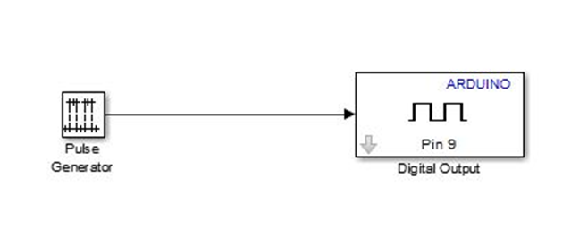
Arduino with Simulink:


8.Click on examples to get this window


13. Later connect the pulse generator and
digital output.
15.Click on tools and select run on target hardware and prepare to
run, it opens configuration parameters dialog there we have to select arduino
uno as target hardware and leave rest of parameters as default and click ok.


Raspberry Pi with Simulink:


When
sent and received packets are same and if the loss is 0% it means Pi is
connected perfectly connected.
Keep
the mode as external as we are connecting an external device.


Interfacing
with Simulink:

Setting the parameters


· If
you want to alter the parameters press stop and then alter.

Making an executable file
1.Type
deploy tool in Matlab command window.

2.
Windows standalone Application window


8.
Give a path for this one so that the package will be placed in specific folder
in the form of executable file.

file

USB 8 relay control in Matlab


Simple Serial interfacing using 8051 Microcontroller and Keil– AT89S52

Smart Home

Hold
down the mouse button and move the cursor to the top input port of the Mux
block.
Now, open the Scope
block to view the simulation output. Keeping the Scope window open, set up
Simulink to run the simulation for 10 seconds. First, set the simulation
parameters by choosing Simulation Parameters from the Simulation menu.
On
the dialog box that appears, notice that the Stop time is set to 10.0 (its
default value).
The simulation stops
when it reaches the stop time specified in the Simulation Parameters dialog box
or when you choose stop from the Simulation menu. To
save this model, choose Save from the File menu and enter a filename and
location. That file contains the description of the model.
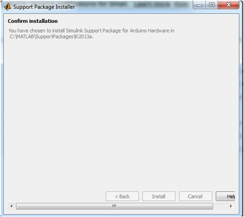
Arduino with Simulink:
Steps
to install Arduino package in Matlab:
1. Home —>Add-on —>Get Hardware support Packages
.
2. Choose the option as internet to download the
package.
3. Tick the check box of which you want to
download. Click on next for option.
4.
Log into your Matlab account for downloading the package.
5.
After login you can find the window as shown.
6.Next an install option will come click install to install
the software
7. Give finish after you download the entire
package.
9.Now
let’s see from scratch how to build Simulink model, just click Simulink library
then you will be appearing with many libraries there we can see our Simulink
arduino package library.
10. In the left there will be option to open new model, open
a new model
11.In this example we are going to use digital output block
,just drag and drop on new model, just double click on this block you will
appearing with in which pin number you are going to show output, give it as 9
click ok.
12. Go to sources library drag and drop pulse generated
block, double click on that give sample time 0.1 and click ok, because it is
going to generate the pulse every one second. We can see that by using scope
which is available in sinks library.
14.Now we shall move on to code generation, save the model
as tutorial1.
16. Now we have to download the code to hardware, just go to
tools and select run on target hardware and run.
17. In the bottom bar of model it is going to show status of
download
18.After the download finishes, at that time LED has to
blink for every second.
Arduino Atmega 320
Hardware
Hardware setup: Arduino Uno
connected to LED via resistor
Raspberry Pi with Simulink:
Software requirements:
MATLAB and Simulink 2013a or higher
Hardware:- Raspberry Pi -RGB Camera-Ethernet cable -Micro
USB cable
When connected to MATLAB and Simulink products, Raspberry Pi also can help students understand concepts and workflows for designing an embedded system, without using hand programming. In this example the camera captures the image which will be connected to Raspberry pi and that image will be inverted and that output is shown in Matlab window.
Example for camera inversion using Raspberry pi
The Raspberry Pi is manufactured in three board
configurations through licensed manufacturing deals with Newark
element14 (Premier Farnell), RS
Components and Egoman. These companies sell the Raspberry Pi online.
Egoman produces a version for distribution solely in China and Taiwan, which
can be distinguished from other Pis by their red coloring and lack of FCC/CE
marks. The hardware is the same across all manufacturers.
Getting Started :
· Automated installation and configuration
· Library of Simulink blocks that connect to Raspberry
Pi I/O, such as audio input and output, video input and display, UDP send and
receive, and GPIO read and write.
· Interactive parameter tuning and signal monitoring of
applications running on Raspberry Pi
Model deployment for standalone operation.
After construction of
the above Simulink model and Hardware arrangement.
Tools—>Run on Target
Hardware —>Options
Set the IP address and
select the particular hardware.
Modeling
with Raspberry Pi
In
command window give ping with above mentioned IP to ping the Hardware with
software.
>>ping
169.254.0.31
Output
Window Raspberry Pi
After
running the program the camera screen will open the output of camera will
inverted as shown in the figure.Now the full operation of inversion is
happening on Raspberry pi and SDL display displays the video on the monitor
Beagle bone Black
Creating a model:
· Home —> Simulink
· Click on Simulink icon then the library window
appears.
· Simulink —>Sources from Simulink library—>Sine
Wave block to the model.
· Connect the output of sine
· wave block to Slider Gain block
· Slider gain block —>Scope
· Save model
Set Sine wave parameter
as shown above
Configuration parameters:
·
Connect BeagleBord hardware with Ethernet network.
·
Click on tools from Simulink window—>Run on Target Hardware à—>prepare to
run
·
Set the IP address as shown below
·
Keep the default values as it is.
·
Press ok to continue.
Run
the model:
· Press
the run button so that the model will run.
· Open
scope to see the result.
Output
Making an executable file
3. After adding all main file and other related
files press build icon.
4. After finishing the building process click on
package to view the complete package.
5. Click on add MCR
option form the package window which appear at the right corner.
6. After pressing ok, click on the package icon
present on the upper right corner.
7. After pressing ok, click on the package icon
present on the upper right corner.
9.This
will install the Matlab package hit on next to complete the process. To run as
executa-ble
HTML View of Script:
To create html view of the code, consider any Matlab file
and add it to your current folder.
Use publish command to generate a html view.
Publish(‘filename.m’);
This executes the code for each cell in filename.m and save
the file to /html/filename.html.
Web (‘html/filename.html’)
USB 8 relay control in Matlab
Brand: RDL
Order Code: RDL/8RB/14/001/V2.0
Product Datasheet: 8-Relay Board Datasheet
Sample
programme
function varargout =
relay_export(varargin)
% RELAY_EXPORT MATLAB code
for relay_export.fig
% RELAY_EXPORT, by itself, creates a new
RELAY_EXPORT or raises the existing
% singleton*.
%
% H = RELAY_EXPORT returns the handle to a
new RELAY_EXPORT or the handle to
% the existing singleton*.
%
%
RELAY_EXPORT('CALLBACK',hObject,eventData,handles,...) calls the local
% function named CALLBACK in RELAY_EXPORT.M
with the given input arguments.
%
% RELAY_EXPORT('Property','Value',...) creates
a new RELAY_EXPORT or raises the
% existing singleton*. Starting from the left, property value pairs
are
% applied to the GUI before
relay_export_OpeningFcn gets called. An
% unrecognized property name or invalid
value makes property application
% stop.
All inputs are passed to relay_export_OpeningFcn via varargin.
%
% *See GUI Options on GUIDE's Tools
menu. Choose "GUI allows only one
% instance to run (singleton)".
%
% See also: GUIDE, GUIDATA,
GUIHANDLES
% Edit the above text to
modify the response to help relay_export
% Last Modified by GUIDE
v2.5 27-Nov-2014 12:28:01
% Begin initialization code - DO NOT EDIT
gui_Singleton = 1;
gui_State = struct('gui_Name', mfilename, ...
'gui_Singleton',
gui_Singleton, ...
'gui_OpeningFcn', @relay_export_OpeningFcn, ...
'gui_OutputFcn',
@relay_export_OutputFcn, ...
'gui_LayoutFcn',
@relay_export_LayoutFcn, ...
'gui_Callback',
[]);
if nargin &&
ischar(varargin{1})
gui_State.gui_Callback = str2func(varargin{1});
end
if nargout
[varargout{1:nargout}] = gui_mainfcn(gui_State, varargin{:});
else
gui_mainfcn(gui_State, varargin{:});
end
% End initialization code -
DO NOT EDIT
% --- Executes just before
relay_export is made visible.
function
relay_export_OpeningFcn(hObject, eventdata, handles, varargin)
% This function has no
output args, see OutputFcn.
% hObject handle to figure
% eventdata reserved - to be defined in a future version
of MATLAB
% handles structure with handles and user data (see
GUIDATA)
% varargin command line arguments to relay_export (see
VARARGIN)
% Choose default command line output for
relay_export
handles.output = hObject;
% Update handles structure
guidata(hObject, handles);
% UIWAIT makes relay_export
wait for user response (see UIRESUME)
% uiwait(handles.figure1);
% --- Outputs from this
function are returned to the command line.
function varargout =
relay_export_OutputFcn(hObject, eventdata, handles)
% varargout cell array for returning output args (see
VARARGOUT);
% hObject handle to figure
% eventdata reserved - to be defined in a future version
of MATLAB
% handles structure with handles and user data (see
GUIDATA)
% Get default command line
output from handles structure
varargout{1} = handles.output;
!ft245RL_Init.exe
global
bin1
bin1 = 0;
% --- Executes on button
press in pushbutton1.
function
pushbutton1_Callback(hObject, eventdata, handles)
% hObject handle to pushbutton1 (see GCBO)
% eventdata reserved - to be defined in a future version
of MATLAB
% handles structure with handles and user data (see
GUIDATA)
global bin1
global flag4
if flag4 == 0
set(handles.pushbutton1, 'BackgroundColor','red')
set(handles.pushbutton1,
'String','Turn
ON Relay 1')
bin1=bitor(bin1,1);
senddata(bin1)
flag4=1;
else
set(handles.pushbutton1, 'BackgroundColor','green')
set(handles.pushbutton1, 'String','Turn OFF
Relay 1')
bin1=bitand(bin1,254);
senddata(bin1)
flag4=0;
end
%set(handles.pushbutton1,
'BackgroundColor','red')
% --- Executes on button
press in pushbutton2.
function
pushbutton2_Callback(hObject, eventdata, handles)
% hObject handle to pushbutton2 (see GCBO)
% eventdata reserved - to be defined in a future version
of MATLAB
% handles structure with handles and user data (see
GUIDATA)
global bin1
global flag4
if flag4 =0
set(handles.pushbutton2, 'BackgroundColor','red')
set(handles.pushbutton2, 'String','Turn ON Relay 2')
bin1=bitor(bin1,2);
senddata(bin1)
flag4=1;
else
bin1=bitand(bin1,253);
senddata(bin1)
set(handles.pushbutton2, 'BackgroundColor','green')
set(handles.pushbutton2, 'String','Turn OFF Relay 2')
flag4=0;
end
% ---
Executes on button press in pushbutton3.
function
pushbutton3_Callback(hObject, eventdata, handles)
% hObject handle to pushbutton3 (see GCBO)
% eventdata reserved - to be defined in a future version
of MATLAB
% handles structure with handles and user data (see
GUIDATA)
global bin1
global flag4
if flag4 == 0
set(handles.pushbutton3, 'BackgroundColor','red')
set(handles.pushbutton3, 'String','Turn ON Relay 3')
bin1=bitor(bin1,4);
senddata(bin1)
flag4=1;
else
set(handles.pushbutton3, 'BackgroundColor','green')
set(handles.pushbutton3, 'String','Turn OFF Relay 3')
bin1=bitand(bin1,251);
senddata(bin1)
flag4=0;
end
% --- Executes on button
press in pushbutton4.
function
pushbutton4_Callback(hObject, eventdata, handles)
% hObject handle to pushbutton4 (see GCBO)
% eventdata reserved - to be defined in a future version
of MATLAB
% handles structure with handles and user data (see
GUIDATA)
global bin1
global flag4
if flag4 == 0
set(handles.pushbutton4, 'BackgroundColor','red')
set(handles.pushbutton4, 'String','Turn ON
Relay 4')
bin1=bitor(bin1,8);
senddata(bin1)
flag4=1;
else
set(handles.pushbutton4, 'BackgroundColor','green')
set(handles.pushbutton4, 'String','Turn OFF Relay 4')
bin1=bitand(bin1,247);
senddata(bin1)
flag4=0;
end
% ---
Executes on button press in pushbutton5.
function
pushbutton5_Callback(hObject, eventdata, handles)
% hObject handle to pushbutton5 (see GCBO)
% eventdata reserved - to be defined in a future version
of MATLAB
% handles structure with handles and user data (see
GUIDATA)
global
bin1
global flag4
if flag4 == 0
set(handles.pushbutton5, 'BackgroundColor','red')
set(handles.pushbutton5, 'String','Turn ON Relay 4')
bin1=bitor(bin1,16);
senddata(bin1)
flag4=1;
else
set(handles.pushbutton5, 'BackgroundColor','green')
set(handles.pushbutton5, 'String','Turn OFF Relay 5')
bin1=bitand(bin1,239);
senddata(bin1)
flag4=0;
end
% ---
Executes on button press in pushbutton6.
function
pushbutton6_Callback(hObject, eventdata, handles)
% hObject handle to pushbutton6 (see GCBO)
% eventdata reserved - to be defined in a future version
of MATLAB
% handles structure with handles and user data (see
GUIDATA)
global bin1
global flag4
if flag4 == 0
set(handles.pushbutton6, 'BackgroundColor','red')
set(handles.pushbutton6, 'String','Turn ON Relay 6')
bin1=bitor(bin1,32);
senddata(bin1)
flag4=1;
else
set(handles.pushbutton6, 'BackgroundColor','green')
set(handles.pushbutton6,
'String','Turn
OFF Relay 6')
bin1=bitand(bin1,223);
senddata(bin1)
flag4=0;
end
% --- Executes on button
press in pushbutton7.
function
pushbutton7_Callback(hObject, eventdata, handles)
% hObject handle to pushbutton7 (see GCBO)
% eventdata reserved - to be defined in a future version
of MATLAB
% handles structure with handles and user data (see
GUIDATA)
global bin1
global flag4
if flag4 == 0
set(handles.pushbutton7, 'BackgroundColor','red')
set(handles.pushbutton7, 'String','Turn ON Relay 7')
bin1=bitor(bin1,64);
senddata(bin1)
flag4=1;
else
set(handles.pushbutton7, 'BackgroundColor','green')
set(handles.pushbutton7, 'String','Turn OFF Relay 7')
bin1=bitand(bin1,191);
senddata(bin1)
flag4=0;
end
% ---
Executes on button press in pushbutton8.
function
pushbutton8_Callback(hObject, eventdata, handles)
% hObject handle to pushbutton8 (see GCBO)
% eventdata reserved - to be defined in a future version
of MATLAB
% handles structure with handles and user data (see
GUIDATA)
global bin1
global flag4
if flag4 == 0
set(handles.pushbutton8, 'BackgroundColor','red')
set(handles.pushbutton8, 'String','Turn ON Relay 8')
bin1=bitor(bin1,128);
senddata(bin1)
flag4=1;
else
set(handles.pushbutton8, 'BackgroundColor','green')
set(handles.pushbutton8, 'String','Turn OFF Relay 8')
bin1=bitand(bin1,127);
senddata(bin1)
flag4=0;
end
% ---
Creates and returns a handle to the GUI figure.
function h1 =
relay_export_LayoutFcn(policy)
% policy - create a new
figure or use a singleton. 'new' or 'reuse'.
persistent hsingleton;
if strcmpi(policy, 'reuse') & ishandle(hsingleton)
h1 = hsingleton;
return;
end
load relay_export.mat
appdata = [];
appdata.GUIDEOptions = mat{1};
appdata.lastValidTag = 'figure1';
appdata.GUIDELayoutEditor = [];
appdata.initTags = struct(...
'handle', [], ...
'tag', 'figure1');
h1 = figure(...
'Units','characters',...
'Color',[0 0 0],...
'Colormap',[0 0 0.5625;0
0 0.625;0 0 0.6875;0 0 0.75;0 0 0.8125;0 0 0.875;0 0 0.9375;0 0 1;0 0.0625 1;0
0.125 1;0 0.1875 1;0 0.25 1;0 0.3125 1;0 0.375 1;0 0.4375 1;0 0.5 1;0 0.5625
1;0 0.625 1;0 0.6875 1;0 0.75 1;0 0.8125 1;0 0.875 1;0 0.9375 1;0 1 1;0.0625 1
1;0.125 1 0.9375;0.1875 1 0.875;0.25 1 0.8125;0.3125 1 0.75;0.375 1
0.6875;0.4375 1 0.625;0.5 1 0.5625;0.5625 1 0.5;0.625 1 0.4375;0.6875 1
0.375;0.75 1 0.3125;0.8125 1 0.25;0.875 1 0.1875;0.9375 1 0.125;1 1 0.0625;1 1
0;1 0.9375 0;1 0.875 0;1 0.8125 0;1 0.75 0;1 0.6875 0;1 0.625 0;1 0.5625 0;1
0.5 0;1 0.4375 0;1 0.375 0;1 0.3125 0;1 0.25 0;1 0.1875 0;1 0.125 0;1 0.0625
0;1 0 0;0.9375 0 0;0.875 0 0;0.8125 0 0;0.75 0 0;0.6875 0 0;0.625 0 0;0.5625 0
0],...
'IntegerHandle','off',...
'InvertHardcopy',get(0,'defaultfigureInvertHardcopy'),...
'MenuBar','none',...
'Name','relay',...
'NumberTitle','off',...
'PaperPosition',get(0,'defaultfigurePaperPosition'),...
'Position',[103.8
42.1538461538462 110.2 19.3076923076923],...
'Resize','off',...
'HandleVisibility','callback',...
'UserData',[],...
'Tag','figure1',...
'Visible','on',...
'CreateFcn',
{@local_CreateFcn, blanks(0), appdata} );
appdata = [];
appdata.lastValidTag = 'pushbutton1';
h2 = uicontrol(...
'Parent',h1,...
'Units','characters',...
'BackgroundColor',[0 1
0],...
'Callback',@(hObject,eventdata)relay_export('pushbutton1_Callback',hObject,eventdata,guidata(hObject)),...
'Position',[5.6
11.7692307692308 20.2 3.84615384615385],...
'String','Turn OFF Relay1',...
'Tag','pushbutton1',...
'CreateFcn',
{@local_CreateFcn, blanks(0), appdata} );
appdata = [];
appdata.lastValidTag = 'pushbutton2';
h3 = uicontrol(...
'Parent',h1,...
'Units','characters',...
'BackgroundColor',[0 1
0],...
'Callback',@(hObject,eventdata)relay_export('pushbutton2_Callback',hObject,eventdata,guidata(hObject)),...
'Position',[29.8
11.6923076923077 18 3.92307692307692],...
'String','Turn OFF Relay 2',...
'Tag','pushbutton2',...
'CreateFcn',
{@local_CreateFcn, blanks(0), appdata} );
appdata = [];
appdata.lastValidTag = 'pushbutton3';
h4 = uicontrol(...
'Parent',h1,...
'Units','characters',...
'BackgroundColor',[0 1
0],...
'Callback',@(hObject,eventdata)relay_export('pushbutton3_Callback',hObject,eventdata,guidata(hObject)),...
'Position',[54.4
11.7692307692308 18 3.84615384615385],...
'String','Turn OFF Relay 3',...
'Tag','pushbutton3',...
'CreateFcn',
{@local_CreateFcn, blanks(0), appdata} );
appdata = [];
appdata.lastValidTag = 'pushbutton4';
h5 = uicontrol(...
'Parent',h1,...
'Units','characters',...
'BackgroundColor',[0 1
0],...
'Callback',@(hObject,eventdata)relay_export('pushbutton4_Callback',hObject,eventdata,guidata(hObject)),...
'Position',[79.8
11.7692307692308 17.6 3.84615384615385],...
'String','Turn OFF Relay 4',...
'Tag','pushbutton4',...
'CreateFcn',
{@local_CreateFcn, blanks(0), appdata} );
appdata = [];
appdata.lastValidTag = 'pushbutton5';
h6 = uicontrol(...
'Parent',h1,...
'Units','characters',...
'BackgroundColor',[0 1
0],...
'Callback',@(hObject,eventdata)relay_export('pushbutton5_Callback',hObject,eventdata,guidata(hObject)),...
'Position',[5.2 4 19.6
3.84615384615385],...
'String','Turn OFF Relay 5',...
'Tag','pushbutton5',...
'CreateFcn',
{@local_CreateFcn, blanks(0), appdata} );
appdata = [];
appdata.lastValidTag = 'pushbutton6';
h7 = uicontrol(...
'Parent',h1,...
'Units','characters',...
'BackgroundColor',[0 1
0],...
'Callback',@(hObject,eventdata)relay_export('pushbutton6_Callback',hObject,eventdata,guidata(hObject)),...
'Position',[29.8 4 17.8
3.84615384615385],...
'String','Turn OFF Relay 6',...
'Tag','pushbutton6',...
'CreateFcn',
{@local_CreateFcn, blanks(0), appdata} );
appdata = [];
appdata.lastValidTag = 'pushbutton7';
h8 = uicontrol(...
'Parent',h1,...
'Units','characters',...
'BackgroundColor',[0 1
0],...
'Callback',@(hObject,eventdata)relay_export('pushbutton7_Callback',hObject,eventdata,guidata(hObject)),...
'Position',[54.4 4 18.2
3.84615384615385],...
'String','Turn OFF Relay 7',...
'Tag','pushbutton7',...
'CreateFcn',
{@local_CreateFcn, blanks(0), appdata} );
appdata = [];
appdata.lastValidTag = 'pushbutton8';
h9 = uicontrol(...
'Parent',h1,...
'Units','characters',...
'BackgroundColor',[0 1
0],...
'Callback',@(hObject,eventdata)relay_export('pushbutton8_Callback',hObject,eventdata,guidata(hObject)),...
'Position',[79.8 4 18
3.84615384615385],...
'String','Turn OFF Relay 8',...
'Tag','pushbutton8',...
'CreateFcn',
{@local_CreateFcn, blanks(0), appdata} );
appdata = [];
appdata.lastValidTag = 'text1';
h10 = uicontrol(...
'Parent',h1,...
'Units','characters',...
'BackgroundColor',[0 0
0],...
'ForegroundColor',[1 0
0],...
'Position',[59.4
1.69230769230769 40.6 1.07692307692308],...
'String','www.researchdesignlab.com',...
'Style','text',...
'Tag','text1',...
'CreateFcn',
{@local_CreateFcn, blanks(0), appdata} );
hsingleton = h1;
% --- Set application data first then calling the
CreateFcn.
function
local_CreateFcn(hObject, eventdata, createfcn, appdata)
if ~isempty(appdata)
names =
fieldnames(appdata);
for i=1:length(names)
name = char(names(i));
setappdata(hObject, name, getfield(appdata,name));
end
end
f ~isempty(createfcn)
if isa(createfcn,'function_handle')
createfcn(hObject, eventdata);
else
eval(createfcn);
end
end
% ---
Handles default GUIDE GUI creation and callback dispatch
function varargout =
gui_mainfcn(gui_State, varargin)
gui_StateFields
= {'gui_Name'
'gui_Singleton'
'gui_OpeningFcn'
'gui_OutputFcn'
'gui_LayoutFcn'
'gui_Callback'};
gui_Mfile = '';
for i=1:length(gui_StateFields)
if ~isfield(gui_State, gui_StateFields{i})
error(message('MATLAB:guide:StateFieldNotFound',
gui_StateFields{ i }, gui_Mfile));
elseif isequal(gui_StateFields{i}, 'gui_Name')
gui_Mfile =
[gui_State.(gui_StateFields{i}), '.m'];
end
end
numargin = length(varargin);
if numargin == 0
% RELAY_EXPORT
% create the GUI only if we are not in the process of
loading it
% already
gui_Create = true;
elseif
local_isInvokeActiveXCallback(gui_State, varargin{:})
% RELAY_EXPORT(ACTIVEX,...)
vin{1} =
gui_State.gui_Name;
vin{2} =
[get(varargin{1}.Peer, 'Tag'), '_', varargin{end}];
vin{3} =
varargin{1};
vin{4} =
varargin{end-1};
vin{5} =
guidata(varargin{1}.Peer);
feval(vin{:});
return;
elseif
local_isInvokeHGCallback(gui_State, varargin{:})
%
RELAY_EXPORT('CALLBACK',hObject,eventData,handles,...)
gui_Create =
false;
else
% RELAY_EXPORT(...)
% create the GUI and hand varargin to the openingfcn
gui_Create = true;
end
if ~gui_Create
% In design time, we need to mark all components
possibly created in
% the coming callback evaluation as non-serializable.
This way, they
% will not be brought into GUIDE and not be saved in
the figure file
% when running/saving the GUI from GUIDE.
designEval =
false;
if (numargin>1 && ishghandle(varargin{2}))
fig =
varargin{2};
while ~isempty(fig) && ~ishghandle(fig,'figure')
fig =
get(fig,'parent');
end
designEval = isappdata(0,'CreatingGUIDEFigure') || isprop(fig,'__GUIDEFigure');
end
if designEval
beforeChildren
= findall(fig);
end
% evaluate the callback now
varargin{1} =
gui_State.gui_Callback;
if nargout
[varargout{1:nargout}] =
feval(varargin{:});
else
feval(varargin{:});
end
% Set serializable of objects created in the above
callback to off in
% design time. Need to check whether figure handle is
still valid in
% case the figure is deleted during the callback
dispatching.
if designEval && ishghandle(fig)
set(setdiff(findall(fig),beforeChildren), 'Serializable','off');
end
else
if gui_State.gui_Singleton
gui_SingletonOpt = 'reuse';
else
gui_SingletonOpt = 'new';
end
% Check user passing 'visible' P/V pair first so that
its value can be
% used by oepnfig to prevent flickering
gui_Visible = 'auto';
gui_VisibleInput =
'';
for index=1:2:length(varargin)
if length(varargin) == index ||
~ischar(varargin{index})
break;
end
% Recognize 'visible' P/V pair
len1 =
min(length('visible'),length(varargin{index}));
len2 =
min(length('off'),length(varargin{index+1}));
if ischar(varargin{index+1}) &&
strncmpi(varargin{index},'visible',len1)
&& len2 > 1
if strncmpi(varargin{index+1},'off',len2)
gui_Visible = 'invisible';
gui_VisibleInput = 'off';
elseif strncmpi(varargin{index+1},'on',len2)
gui_Visible = 'visible';
gui_VisibleInput = 'on';
end
end
end
% Open fig
file with stored settings. Note: This
executes all component
% specific CreateFunctions with an empty HANDLES
structure.
% Do feval on layout code in m-file if it exists
gui_Exported =
~isempty(gui_State.gui_LayoutFcn);
% this application data is used to indicate the
running mode of a GUIDE
% GUI to distinguish it from the design mode of the
GUI in GUIDE. it is
% only used by actxproxy at this time.
setappdata(0,genvarname(['OpenGuiWhenRunning_',
gui_State.gui_Name]),1);
if gui_Exported
gui_hFigure =
feval(gui_State.gui_LayoutFcn, gui_SingletonOpt);
% make figure invisible here so that the visibility
of figure is
%
consistent in OpeningFcn in the exported GUI case
if
isempty(gui_VisibleInput)
gui_VisibleInput = get(gui_hFigure,'Visible');
end
set(gui_hFigure,'Visible','off')
% openfig (called by local_openfig below) does this
for guis without
% the LayoutFcn. Be sure to do it here so guis show
up on screen.
movegui(gui_hFigure,'onscreen');
else
gui_hFigure =
local_openfig(gui_State.gui_Name, gui_SingletonOpt, gui_Visible);
% If the figure has InGUIInitialization it was not
completely created
% on the last pass.
Delete this handle and try again.
if isappdata(gui_hFigure, 'InGUIInitialization')
delete(gui_hFigure);
gui_hFigure = local_openfig(gui_State.gui_Name, gui_SingletonOpt,
gui_Visible);
end
end
if isappdata(0, genvarname(['OpenGuiWhenRunning_',
gui_State.gui_Name]))
rmappdata(0,genvarname(['OpenGuiWhenRunning_',
gui_State.gui_Name]));
end
% Set flag to indicate starting GUI initialization
setappdata(gui_hFigure,'InGUIInitialization',1);
% Fetch GUIDE Application options
gui_Options =
getappdata(gui_hFigure,'GUIDEOptions');
% Singleton setting in the GUI M-file takes priority
if different
gui_Options.singleton = gui_State.gui_Singleton;
if ~isappdata(gui_hFigure,'GUIOnScreen')
% Adjust background color
if gui_Options.syscolorfig
set(gui_hFigure,'Color', get(0,'DefaultUicontrolBackgroundColor'));
end
% Generate HANDLES structure and store with GUIDATA.
If there is
% user set GUI data already, keep that also.
data =
guidata(gui_hFigure);
handles = guihandles(gui_hFigure);
if ~isempty(handles)
if isempty(data)
data =
handles;
else
names
= fieldnames(handles);
for k=1:length(names)
data.(char(names(k)))=handles.(char(names(k)));
end
end
end
guidata(gui_hFigure, data);
end
% Apply input P/V pairs other than 'visible'
for index=1:2:length(varargin)
if length(varargin) == index ||
~ischar(varargin{index})
break;
end
len1 = min(length('visible'),length(varargin{index}));
if ~strncmpi(varargin{index},'visible',len1)
try set(gui_hFigure, varargin{index}, varargin{index+1}),
catch break, end
end
end
% If
handle visibility is set to 'callback', turn it on until finished
% with OpeningFcn
gui_HandleVisibility = get(gui_hFigure,'HandleVisibility');
if strcmp(gui_HandleVisibility, 'callback')
set(gui_hFigure,'HandleVisibility', 'on');
end
feval(gui_State.gui_OpeningFcn, gui_hFigure, [], guidata(gui_hFigure),
varargin{:});
if isscalar(gui_hFigure) &&
ishghandle(gui_hFigure)
% Handle the default callbacks of predefined toolbar
tools in this
% GUI, if any
guidemfile('restoreToolbarToolPredefinedCallback',gui_hFigure);
% Update
handle visibility
set(gui_hFigure,'HandleVisibility',
gui_HandleVisibility);
% Call
openfig again to pick up the saved visibility or apply the
% one passed in from the P/V pairs
if ~gui_Exported
gui_hFigure =
local_openfig(gui_State.gui_Name, 'reuse',gui_Visible);
elseif ~isempty(gui_VisibleInput)
set(gui_hFigure,'Visible',gui_VisibleInput);
end
if strcmpi(get(gui_hFigure, 'Visible'),
'on')
figure(gui_hFigure);
if
gui_Options.singleton
setappdata(gui_hFigure,'GUIOnScreen',
1);
end
end
% Done with GUI initialization
if isappdata(gui_hFigure,'InGUIInitialization')
rmappdata(gui_hFigure,'InGUIInitialization');
end
% If handle visibility is set to 'callback', turn it
on until
% finished with OutputFcn
gui_HandleVisibility = get(gui_hFigure,'HandleVisibility');
if strcmp(gui_HandleVisibility, 'callback')
set(gui_hFigure,'HandleVisibility', 'on');
end
gui_Handles =
guidata(gui_hFigure);
else
gui_Handles =
[];
end
if nargout
[varargout{1:nargout}] = feval(gui_State.gui_OutputFcn, gui_hFigure, [],
gui_Handles);
else
feval(gui_State.gui_OutputFcn, gui_hFigure, [], gui_Handles);
end
if isscalar(gui_hFigure) && ishghandle(gui_hFigure)
set(gui_hFigure,'HandleVisibility',
gui_HandleVisibility);
end
end
function gui_hFigure =
local_openfig(name, singleton, visible)
% openfig with three arguments was new from R13. Try
to call that first, if
% failed, try the old openfig.
if nargin('openfig') == 2
% OPENFIG did not accept 3rd input argument until
R13,
% toggle default figure visible to prevent the figure
% from showing up too soon.
gui_OldDefaultVisible = get(0,'defaultFigureVisible');
set(0,'defaultFigureVisible','off');
gui_hFigure =
openfig(name, singleton);
set(0,'defaultFigureVisible',gui_OldDefaultVisible);
else
gui_hFigure =
openfig(name, singleton, visible);
%workaround for CreateFcn not called to create
ActiveX
if feature('HGUsingMATLABClasses')
peers=findobj(findall(allchild(gui_hFigure)),'type','uicontrol','style','text');
for i=1:length(peers)
if isappdata(peers(i),'Control')
actxproxy(peers(i));
end
end
end
end
function result =
local_isInvokeActiveXCallback(gui_State, varargin)
try
result = ispc
&& iscom(varargin{1}) ...
&& isequal(varargin{1},gcbo);
catch
result = false;
end
function result =
local_isInvokeHGCallback(gui_State, varargin)
try
fhandle =
functions(gui_State.gui_Callback);
result =
~isempty(findstr(gui_State.gui_Name,fhandle.file)) || ...
(ischar(varargin{1}) ...
&& isequal(ishghandle(varargin{2}), 1) ...
&& (~isempty(strfind(varargin{1},[get(varargin{2}, 'Tag'), '_']))
|| ...
~isempty(strfind(varargin{1}, '_CreateFcn')))
);
catch
result = false;
end
senddata code
function senddata(val1)
%colorc='r'
disp('BEGIN')
ser=serial('COM3');
set(ser,'BaudRate',9600);
set(ser,'DataBits',8);
set(ser,'Parity','none');
set(ser,'StopBits',1);
set(ser,'FlowControl','none');
set(ser,'Terminator','CR/LF');
fopen(ser);
val1
%if colorc=='Q'
%
for i=1:1000
% fprintf(ser,'%c',colorc);
fwrite(ser,val1,'uint8');
%
end
%end
fclose(ser);
delete(ser);
%clear all;
disp('STOP');
Important steps to execute relay
·
We
have to paste ftd2xx.dll and kernel32.dll files in C (create WINNT file inside
that again create System32 file and paste those files here).
·
Before
running the code in matlab make sure that u installed FT245RLutility software.
·
Make
sure that you have given same serial port number in senddata which you have
connected the relay
Embedded
part with programming
Programming the 8051 to receive character bytes serially
1. TMOD register is loaded with the value TMOD=0X20,
indicating the use of timer 1 in mode2
(8-bit auto-reload) to set baud rate
2. TH1 is loaded to set baud rate
3. The SCON register is loaded with the value
SCON=0X50, indicating serial mode 1, where an 8-bit data is framed with start
and stop bits
4. TR1 is set to 1 to start timer 1
5. RI is cleared by RI=0; RI instruction
6. The RI flag bit is monitored with the use of
instruction while (RI==0); to see if an entire character has been received yet.
7. When RI is raised, SBUF has the byte, its
contents are moved into a safe place
8. To receive the next character, go to step 5
Simple Serial interfacing using 8051 Microcontroller and Keil– AT89S52
Fig.5 shows the
circuit of simple 8051 Microcontroller interfaced with LED’s.
Here is a simple
Embedded C program for interfacing 8 LED’s to a 8051 Microcontroller which
could be turned ON or OFF by sending few
serial commands.
Program 5 enables a user to turn ON/OFF a series of LED’s by
sending serial data. The program is designed in such a way that a serial
command A1 will turn ON the first LED and A0 will turn of the same LED.
Similarly B1 will turn ON the second LED and B0 will turn of the same LED. This
will continue for the remaining 6 LED’s. i.e. H1 and H0 would turn ON and OFF
last LED (8th LED) respectively. You
can enter the inputs in any serial window monitor software like Hyperterminal, Putty
etc. Also you could design a GUI in software like Matlab, .NET etc. which could
be used to control these LED’s.
Components/modules required
1) 8051
project board with RS232 interface (assembled/non assembled kit).
2) 5V DC
source.
3) 8 LED’s.
4) Resistors
(1KΩx8).
5) IC AT89S52.
6) 8051 IC burner.
7) Connectors and cables.
Fig. 5 Circuit Diagram for Serial and LED interfacing
Program 5:
#include<reg52.h> //special function register
declarations
//for
the intended 8051 derivative
void delay(); // Function prototype declaration
sbit LED0=P2^0; //Define Port Pin P2.0 as LED0
sbit LED1=P2^1; //Define Port Pin P2.1 as LED1
sbit LED2=P2^2; //Define Port Pin P2.2 as LED2
sbit LED3=P2^3; //Define Port Pin P2.3 as LED3
sbit LED4=P2^4; //Define Port Pin P2.4 as LED4
sbit LED5=P2^5; //Define Port Pin P2.5 as LED5
sbit LED6=P2^6; //Define Port Pin P2.6 as LED6
sbit LED7=P2^7; //Define Port Pin P2.7 as LED7
Unsigned char byte1,byte2; //
Variable declarations
/ MAIN CODE
void
main()
{
//Serial Initialization
TMOD=0X20; //use
Timer 1, mode 2
SCON=0X50;
//indicating
serial mode 1, where an 8-bit
//data
is framed with start and stop bits
TH1=0XFD; //9600 baud rate
TR1=1;
//Start
timer
delay(); //Wait for a delay for serial initialization to finish
// transmit 'S' to check whether the setup is ready
TI=0; //Forcibly change the Transmit Interrupt Flag of 8051 to
0
SBUF='S';
//Move
'S' to serial buffer memory
While
(TI==0); //Wait until TI flag is set by hardware when an entire
byte
//has
been transmitted
TI=0;
//
Forcibly clear TI flag
delay
(); //A small delay for relaxation
P2=0x00;
//Set Port 2 all bits to 0
while
(1) //
continuous loop
{
RI=0;
//Forcibly
clear the Receive Interrupt Flag of 8051 to 0
while(RI==0);
//Wait
until RI flag is set by hardware when an entire byte
//has
been received
byte1=SBUF; //Move the
received byte of data into variable 'byte1'
RI=0;
//Forcibly clear RI flag
While(RI==0);
//Wait
until RI flag is set by //hardware
when an entire byte
//has
been received
byte2=SBUF; //Move the
received byte of data //into
variable 'byte2'
RI=0; //Forcibly clear
RI flag
delay();
delay();
If(byte1=='A') //Check whether the
1st byte of
{ //data
is 'A'
if(byte2=='1') //Check whether
the 2nd byte of
{ //data
is '1'
LED0=1; //Turn ON LED0
delay(); //Wait
for a small delay
}
else
if(byte2=='0') //Check whether the 2nd byte of
{ //data
is '0'
LED0=0; //Turn OFF LED0
delay
(); //Wait for a small delay
}
}
else
if(byte1=='B') //Check whether the 1st byte of
{ //data
is 'B'
if(byte2=='1') //Check whether
the 2nd byte of
{ //data
is '1'
else
if(byte2=='0') //Check whether the 2nd byte of
{ //data
is '0'
LED1=0; //Turn
OFF LED1
delay
(); //Wait for a small delay
}
}
else
if(byte1=='C') //Check whether the 1st byte of
{ //data
is 'C'
if(byte2=='1') //Check whether
the 2nd byte of
{ //data
is '1'
LED2=1; //Turn ON LED2
delay(); //Wait
for a small delay
}
else
if(byte2=='0') //Check whether the 2nd byte of
{ //data
is '0'
LED2=0; //Turn OFF LED2
delay(); //Wait
for a small delay
}
}
else
if(byte1=='D') //Check whether the 1st byte of
{ //data
is 'D'
if(byte2=='1') //Check whether
the 2nd byte of
{ //data
is '1'
delay(); //Wait
for a small delay
}
else
if(byte2=='0') //Check whether the 2nd byte of
{ //data
is '0'
LED3=0; //Turn OFF LED3
delay(); //Wait
for a small delay
}
}
else
if(byte1=='E') //Check whether the 1st byte of
{ //data is 'E'
if(byte2=='1') //Check whether
the 2nd byte of
{ //data
is '1'
LED4=1; //Turn ON LED4
delay(); //Wait
for a small delay
}
else
if(byte2=='0') //Check whether the 2nd byte of
{ //data
is '0'
LED4=0; //Turn OFF LED4
delay(); //Wait
for a small delay
}
}
else
if(byte1=='F') //Check whether the 1st byte of
{
//data is 'F'
if(byte2=='1') //Check whether
the 2nd byte of
{ //data
is '1'
LED5=1; //Turn ON LED5
delay(); //Wait
for a small delay
}
else
if(byte2=='0') //Check whether the 2nd byte of
{ //data
is '0'
LED5=0; //Turn OFF LED5
delay(); //Wait
for a small delay
}
}
else
if(byte1=='G') //Check whether the 1st byte of
{ //data
is 'G'
if(byte2=='1') //Check whether
the 2nd byte of
{ //data
is '1'
LED6=1; //Turn ON LED6
delay(); //Wait
for a small delay
}
else
if(byte2=='0') //Check whether the 2nd byte of
{ //data
is '0'
LED6=0; //Turn OFF LED6
delay(); //Wait
for a small delay
}
}
else
if(byte1=='H') //Check whether the 1st byte of
{ //data
is 'H'
if(byte2=='1') //Check whether
the 2nd byte of { //data is '1'
LED7=1; //Turn ON LED7
delay(); //Wait
for a small delay
}
else
if(byte2=='0') //Check whether the 2nd byte of
{ //data
is '0'
LED7=0; //Turn OFF LED7
delay(); //Wait
for a small delay
}
}
else
{
P2=0x00; //Set Port 2 all bits to 0 if any
//other
variable has been received
delay(); //Wait
for a small delay
}
}
}
void
delay() // Delay Routine
{
unsigned int x=60000; // larger the value of x
//the
more is the delay.
while (x--); // executes this statement
} //until
x decrements to 0
Smart Home
WORKING:
The
matlab gui is programmed in such a way that whenever you click the push button
it sends a serial interrupt to the microcontroller via RS232 protocol. The
microcontroller is programmed in such a way that for a particular interrupt a
particular task is done.
The microcontroller is used to monitor
and control the devices. An embedded c
program is pre written into the microcontroller which is programmed according
to our need. The microcontroller is then
interfaced with the relays and the necessary water level sensors. Matlab will send a serial data to the
microcontroller via the serial interface. The microcontroller replies if
necessary and does the task assigned to it.
There are two parts in the matlabGui,
one will behave like a regular user interface for hardware controlling the
other will detect motion and fire through camera vision. Matlab will send an
email to the concern user if any threat was detected along with a snapshot of
the current view.
Program embedded code
char
DATA1,DATA2;
sbit
relay1 at RB0_bit;
sbit
relay2 at RB1_bit;
sbit
relay3 at RB2_bit;
sbit
relay4 at RB3_bit;
sbit
relay5 at RB4_bit;
//sbit W0 at RD4_bit;
sbit
W1 at RD5_bit;
sbit
W2 at RD6_bit;
sbit
W3 at RD7_bit;
sbit
check1 at RD2_bit;
void
main() {
TRISB
= 0x00;
TRISD2_bit=0;
//TRISD4_bit=1;
TRISD5_bit=1;
TRISD6_bit=1;
TRISD7_bit=1;
UART1_Init(9600); //
Initialize UART module at 9600 bps
Delay_ms(100);
check1=0;
PORTB=0x00;
while(1)
{
while(!UART1_Data_Ready());
DATA1=UART1_Read();
if (DATA1 == '1')
{
while(!UART1_Data_Ready());
DATA2=UART1_Read();
if (DATA2 == '1')
{
relay1=1;
}
else if (DATA2 == '0')
{
relay1=0;
}
}
else if (DATA1
== '2')
{
while(!UART1_Data_Ready());
DATA2=UART1_Read();
if (DATA2 == '1')
{
relay2=1;
}
}
else if (DATA1 == '3')
{
While(!UART1_Data_Ready());
DATA2=UART1_Read();
if (DATA2 == '1')
{
relay3=1;
}
else if (DATA2 == '0')
{
relay3=0;
}
}
else if (DATA1 == '4')
{
while(!UART1_Data_Ready());
DATA2=UART1_Read();
if (DATA2 == '1')
{
relay4=1;
}
else if (DATA2 == '0')
{
relay4=0;
}
}
else if (DATA1 == '5')
{
while(!UART1_Data_Ready());
DATA2=UART1_Read();
if (DATA2 == '1')
{
relay5=1;
}
else if (DATA2
== '0')
{
relay5=0;
}
}
else if (DATA1 == 'W')
{
while(!UART1_Data_Ready());
DATA2=UART1_Read();
if (DATA2 == 'T')
{
if (W1 == 1 && W2 == 1 &&
W3 ==1)
{
UART1_Write_Text("L3");
UART1_Write(10);
UART1_Write(13);
}
else if (W1 == 1
&& W2 == 1 && W3 ==0)
{
UART1_Write_Text("L2");
UART1_Write(10);
UART1_Write(13);
}
else if (W1 == 1 && W2 == 0
&& W3 ==0)
{
UART1_Write_Text("L1");
UART1_Write(10);
UART1_Write(13);
}
else if (W1 == 0 && W2 == 0
&& W3 ==0)
{
UART1_Write_Text("L0");
UART1_Write(10);
UART1_Write(13);
}
}
}
else
{
PORTB=0x00;
}
}}
Sample Matlab
GUI Program
function varargout = SMART_HOME(varargin)
% SMART_HOME M-file for SMART_HOME.fig
% SMART_HOME, by
itself, creates a new SMART_HOME or raises the existing
% singleton*.
%
% H = SMART_HOME
returns the handle to a new SMART_HOME or the handle to
% the existing
singleton*.
%
% SMART_HOME('CALLBACK',hObject,eventData,handles,...)
calls the local
% function named
CALLBACK in SMART_HOME.M with the given input arguments.
%
%
SMART_HOME('Property','Value',...) creates a new SMART_HOME or raises
the
% existing
singleton*. Starting from the left,
property value pairs are
% applied to the
GUI before SMART_HOME_OpeningFcn gets called.
An
% unrecognized
property name or invalid value makes property application
% stop. All inputs are passed to SMART_HOME_OpeningFcn
via varargin.
%
% *See GUI
Options on GUIDE's Tools menu. Choose
"GUI allows only one
% instance to run
(singleton)".
%
% See also: GUIDE, GUIDATA, GUIHANDLES
% Edit the above text to modify the response to help
SMART_HOME
% Last Modified by GUIDE v2.5 08-Dec-2012 18:37:11
% Begin initialization code - DO NOT EDIT
gui_Singleton = 1;
gui_State = struct('gui_Name', mfilename, ...
'gui_Singleton', gui_Singleton, ...
'gui_OpeningFcn',
@SMART_HOME_OpeningFcn, ...
'gui_OutputFcn', @SMART_HOME_OutputFcn, ...
'gui_LayoutFcn', [] , ...
'gui_Callback', []);
if nargin && ischar(varargin{1})
gui_State.gui_Callback =
str2func(varargin{1});
end
if nargout
[varargout{1:nargout}] =
gui_mainfcn(gui_State, varargin{:});
else
gui_mainfcn(gui_State,
varargin{:});
end
% End initialization code - DO NOT EDIT
% --- Executes just before SMART_HOME is made visible.
function SMART_HOME_OpeningFcn(hObject, eventdata, handles, varargin)
% This function has no output args, see OutputFcn.
% hObject handle to
figure
% eventdata reserved
- to be defined in a future version of MATLAB
% handles structure
with handles and user data (see GUIDATA)
% varargin command
line arguments to SMART_HOME (see VARARGIN)
% Choose default command line output for SMART_HOME
handles.output = hObject;
% Update handles structure
guidata(hObject, handles);
% UIWAIT makes SMART_HOME wait for user response (see
UIRESUME)
% uiwait(handles.figure1);
% --- Outputs from this function are returned to the command
line.
function varargout = SMART_HOME_OutputFcn(hObject, eventdata, handles)
% varargout cell
array for returning output args (see VARARGOUT);
% hObject handle to
figure
% eventdata reserved
- to be defined in a future version of MATLAB
% handles structure
with handles and user data (see GUIDATA)
% Get default command line output from handles structure
varargout{1} = handles.output;
global flag1
global flag2
global flag3
global flag4
global flag5
global ser
global
FanOff
global FanOn
global BulbOff
global BulbOn
global unlock
global lock
global SpeakersOff
global SpeakersOn
clc
%% initialise serial port
ser=serial('COM2');
set(ser,'BaudRate',9600);
set(ser,'DataBits',8);
set(ser,'Parity','none');
set(ser,'StopBits',1);
set(ser,'FlowControl','none');
set(ser, 'Timeout', 2)
set(ser,'Terminator','CR/LF');
%%
%% load all the images required to be displayed
pump =imread('water-pump1.jpg');
FanOff=imread('FanOff.jpg');
FanOn=imread('FanON.jpg');
axes(handles.axes1);
imshow(FanOff);
BulbOff=imread('BulbOff.jpg');
BulbOn=imread('BulbOn.jpg');
axes(handles.axes2);
imshow(BulbOff);
unlock=imread('unlock.jpg');
lock=imread('lock.jpg');
axes(handles.axes3);
imshow(unlock);
SpeakersOff=imread('SpeakersOff.jpg');
SpeakersOn=imread('SpeakersOn.jpg');
axes(handles.axes4);
imshow(SpeakersOff);
axes(handles.axes5);
imshow(pump);
set(handles.pushbutton1, 'BackgroundColor','green')
set(handles.pushbutton2, 'BackgroundColor','green')
set(handles.pushbutton3, 'BackgroundColor','green')
set(handles.pushbutton4, 'BackgroundColor','green')
set(handles.text3, 'visible','off')
set(handles.text4, 'visible','off')
set(handles.text5, 'visible','off')
set(handles.text6, 'visible','off')
flag1 = 0;
flag2 = 0;
flag3 = 0;
flag4 = 0;
flag5 = 0;
% --- Executes on button press in pushbutton1.
function pushbutton1_Callback(hObject, eventdata, handles)
% hObject handle to
pushbutton1 (see GCBO)
% eventdata reserved
- to be defined in a future version of MATLAB
% handles structure
with handles and user data (see GUIDATA)
global flag1
global FanOff
global FanOn
global ser
fopen(ser);
if flag1 == 0
set(handles.pushbutton1, 'BackgroundColor','red')
% pval(1)=1
fprintf(ser,'%s','11');
flag1=1;
axes(handles.axes1);
imshow(FanOn);
else
set(handles.pushbutton1,
'BackgroundColor','green')
% pval(1)=0
fprintf(ser,'%s','10');
flag1=0;
axes(handles.axes1);
imshow(FanOff);
end
% putvalue(parport1,pval);
fclose(ser)
% --- Executes on button press in pushbutton2.
function pushbutton2_Callback(hObject, eventdata, handles)
% hObject handle to
pushbutton2 (see GCBO)
% eventdata reserved
- to be defined in a future version of MATLAB
% handles structure
with handles and user data (see GUIDATA)
global
flag2
global ser
global BulbOff
global BulbOn
fopen(ser)
if flag2 == 0
set(handles.pushbutton2, 'BackgroundColor','red')
% pval(2)=1
fprintf(ser,'%s','21');
flag2=1;
axes(handles.axes2);
imshow(BulbOn);
else
set(handles.pushbutton2,
'BackgroundColor','green')
% pval(2)=0
fprintf(ser,'%s','20');
flag2=0;
axes(handles.axes2);
imshow(BulbOff);
end
fclose(ser)
% --- Executes on button press in pushbutton3.
function pushbutton3_Callback(hObject, eventdata, handles)
% hObject handle to
pushbutton3 (see GCBO)
% eventdata reserved
- to be defined in a future version of MATLAB
% handles structure
with handles and user data (see GUIDATA)
global flag3
global ser
global unlock
global lock
fopen(ser)
if
flag3 == 0
set(handles.pushbutton3, 'BackgroundColor','red')
% pval(3)=1
fprintf(ser,'%s','31');
flag3=1;
axes(handles.axes3);
imshow(lock);
else
set(handles.pushbutton3,
'BackgroundColor','green')
% pval(3)=0
fprintf(ser,'%s','30');
flag3=0;
axes(handles.axes3);
imshow(unlock);
end
fclose(ser)
% --- Executes on button press in pushbutton4.
function pushbutton4_Callback(hObject, eventdata, handles)
% hObject handle to
pushbutton4 (see GCBO)
% eventdata reserved
- to be defined in a future version of MATLAB
% handles structure
with handles and user data (see GUIDATA)
global
flag4
global ser
global SpeakersOff
global SpeakersOn
fopen(ser)
if flag4 == 0
set(handles.pushbutton4, 'BackgroundColor','red')
% pval(4)=1
fprintf(ser,'%s','41');
flag4=1;
axes(handles.axes4);
imshow(SpeakersOn);
else
set(handles.pushbutton4,
'BackgroundColor','green')
% pval(4)=0
fprintf(ser,'%s','40');
flag4=0;
axes(handles.axes4);
imshow(SpeakersOff);
end
fclose(ser)
% --- Executes on button press in pushbutton5.
function pushbutton5_Callback(hObject, eventdata, handles)
% hObject handle to
pushbutton5 (see GCBO)
% eventdata reserved
- to be defined in a future version of MATLAB
% handles structure
with handles and user data (see GUIDATA)
global ser
fclose(ser)
close all
% --- Executes on button press in pushbutton6.
function pushbutton6_Callback(hObject, eventdata, handles)
% hObject handle to
pushbutton6 (see GCBO)
% eventdata reserved
- to be defined in a future version of MATLAB
% handles structure
with handles and user data (see GUIDATA)
global ser
set(handles.text3, 'visible','off')
set(handles.text4, 'visible','off')
set(handles.text5, 'visible','off')
set(handles.text6, 'visible','off')
%% check sensor status and display the level of contents in
the tank.
fopen(ser);
fprintf(ser,'%s','WT');
acc=fscanf(ser);
fclose(ser)
Val = strtrim(acc)
checkdata = isempty(Val)
if
checkdata ~= 1
TF1 = strncmp('L1',
Val, 2);
TF2 = strncmp('L2',
Val, 2);
TF3 = strncmp('L3',
Val, 2);
TF4 = strncmp('L4',
Val, 2);
TF5 = strncmp('L0',
Val, 2);
if
(TF1==1)
set(handles.text6, 'visible','on')
elseif
(TF2==1)
set(handles.text6, 'visible','on')
set(handles.text5, 'visible','on')
elseif
(TF3==1)
set(handles.text6, 'visible','on')
set(handles.text5, 'visible','on')
set(handles.text4, 'visible','on')
elseif
(TF4==1)
set(handles.text6, 'visible','on')
set(handles.text5, 'visible','on')
set(handles.text4, 'visible','on')
set(handles.text3, 'visible','on')
elseif
(TF5==1)
set(handles.text6, 'visible','off')
set(handles.text5, 'visible','off')
set(handles.text4, 'visible','off')
set(handles.text3, 'visible','off')
end
else
end
% --- Executes on button press in pushbutton7.
function pushbutton7_Callback(hObject, eventdata, handles)
% hObject handle to
pushbutton7 (see GCBO)
% eventdata reserved
- to be defined in a future version of MATLAB
% handles structure
with handles and user data (see GUIDATA)
global ser
global flag5
fopen(ser);
if flag5 == 0
set(handles.pushbutton7, 'BackgroundColor','red')
% pval(5)=1;
fprintf(ser,'%s','51');
flag5=1;
else
set(handles.pushbutton7,
'BackgroundColor','green')
% pval(5)=0
fprintf(ser,'%s','50');
flag5=0;
end
fclose(ser)
All the codes are available in link mention below