Pages

Sunday 6 December 2015

SSR 230V/8A Dimmer-ON/OFF Switch

OVERVIEW:

The  SSR switch  ON / OFF and  16 level Dimming can be controlled using controller , switches  and PLC logics .This switch can be used control light , FAN, power socket ,  Triac dimming enabled LED's and any other remote  ON / OFF  or dimming application.

Features:


  • On/Off  and dimming control.
  • Snubber circuit enable.
  • Accurate firing angle control and smooth dimming.
  • Operating Voltage 5V DC.
  • Isolated power section from the input.
  • 0-100% dimming.
  • Typical Power handling upto 1800Watts.
  • Maximum power handling 2760Watts *.
  • High quality PCB FR4 Grade with FPT Certified.
BTA12 Triac Features:

  • Blocking Voltage to 800 V
  • On-State Current Rating of 12 A RMS at 25°C
  • Uniform Gate Trigger Currents in Three Quadrants
  • High Immunity to dV/dt − 1500 V/s minimum at 125°C
  • Minimizes Snubber Networks for Protection
  • Industry Standard TO-220AB Package
  • High Commutating dI/dt − 1.5 A/ms minimum at 125°C
  • Internally Isolated (2500 VRMS)
  • These Devices are Pb−Free and are RoHS Compliant*
For More Schematic and Codes: CLICK HERE

Thursday 3 December 2015

Bluetooth-SSR 230V/8A Dimmer-ON/OFF Switch

OVERVIEW:

The board can be used in applications where dimming of 230V/50Hz AC power is required like dimming of bulb or fan.
FEATURES:


  • On/Off  and dimming control.
  • Snubber circuit enable.
  • Accurate firing angle control and smooth dimming.
  • Operating Voltage 5V DC.
  • Isolated power section from the input.
  • 0-100% dimming.
  • Bluetooth Enabled.
  • Typical Power handling upto 1800Watts.
  • Maximum power handling 2760Watts *.
  • High quality PCB FR4 Grade with FPT Certified.

BTA12 Triac Features:

  • Blocking Voltage to 800 V
  • On-State Current Rating of 12 A RMS at 25°C
  • Uniform Gate Trigger Currents in Three Quadrants
  • High Immunity to dV/dt − 1500 V/s minimum at 125°C
  • Minimizes Snubber Networks for Protection
  • Industry Standard TO-220AB Package
  • High Commutating dI/dt − 1.5 A/ms minimum at 125°C
  • Internally Isolated (2500 VRMS)
  • These Devices are Pb−Free and are RoHS Compliant*
FOR MORE SCHEMATICS AND SAMPLE CODE: CLICK HERE


WiFi-SSR 230V/8A Dimmer-ON/OFF Switch


OVERVIEW:

The board can be used in applications where dimming of 230V/50Hz AC power is required like dimming of bulb or fan.

FEATURES:

  • On/Off  and dimming control.
  • Snubber circuit enable.
  • Accurate firing angle control and smooth dimming.
  • Operating Voltage 5V DC.
  • Isolated power section from the input.
  • 0-100% dimming.
  • WiFi Enabled.
  • Typical Power handling upto 1800Watts.
  • Maximum power handling 2760Watts *.
  • High quality PCB FR4 Grade with FPT Certified.

ESP8266 ESP-07 Features:

  • SDIO 2.0, SPI, UART
  •     32-pin QFN package
  •     Integrated RF switch, balun, 24dBm PA, DCXO, and PMU
  •     Integrated RISC processor, on-chip memory and external memory interfaces
  •     Integrated MAC/baseband processors
  •     Quality of Service management
  •     I2S interface for high fidelity audio applications
  •     On-chip low-dropout linear regulators for all internal supplies
  •     Proprietary spurious-free clock generation architecture
  •     Integrated WEP, TKIP, AES, and WAPI engines.
ESP8266 ESP-07 Specifications:
  •     802.11 b/g/n
  •     Wi-Fi Direct (P2P), soft-AP
  •     Integrated TCP/IP protocol stack
  •     Integrated TR switch, balun, LNA, power amplifier and matching network
  •     Integrated PLLs, regulators, DCXO and power management units
  •     +19.5dBm output power in 802.11b mode
  •     Power down leakage current of <10uA
  •     Integrated low power 32-bit CPU could be used as application processor
  •     SDIO 1.1/2.0, SPI, UART
  •     STBC, 1×1 MIMO, 2×1 MIMO
  •     A-MPDU & A-MSDU aggregation & 0.4ms guard interval
  •     Wake up and transmit packets in < 2ms
  •     Standby power consumption of < 1.0mW (DTIM3).
BTA12 Triac Features:
  • Blocking Voltage to 800 V
  • On-State Current Rating of 12 A RMS at 25°C
  • Uniform Gate Trigger Currents in Three Quadrants
  • High Immunity to dV/dt − 1500 V/s minimum at 125°C
  • Minimizes Snubber Networks for Protection
  • Industry Standard TO-220AB Package
  • High Commutating dI/dt − 1.5 A/ms minimum at 125°C
  • Internally Isolated (2500 VRMS)
  • These Devices are Pb−Free and are RoHS Compliant*
For More Schematic and Sample Codes: CLICK HERE

Bluetooth Robo UNO Atmega328 Development Board


OVERVIEW:

Open source Bluetooth Robot Hardware is intended to serve as a resource for efforts focusing on Open and Open Source mechanical ,electrical  and mobile application integration , with a particular focus on projects that may be useful in robotics applications, robotics research and education.


PRODUCT DESCRIPTION:

Robot is controlled by a android mobile phone with remote control application installed. Initially both the Bluetooth devices should be paired.If any button is pressed a byte corresponding to the button presses is received at the other end of the Bluetooth receiver. The microcontroller is programmed to take appropriate movement action for a given input. These decisions will be used to driver the motors forward, backward, left and right via l298 motor driver.

For more Schematics and Sample Codes: Click Here

Monday 26 October 2015

SPY BEAGLE BOT DIY KIT


OVERVIEW:

Spy robots are remotely controlled robots, equipped with a camera, transmitting video data to the remote area. A movable spy robot with a remote controller by using beagle bone. The spy robot is made up of a USB camera, Wi-Fi adaptor, batteries and movable wheels. To remotely control wireless system and to control Spy robot Wi-Fi technology is used.
Remote Operated Spy Robot is a small robot designed for spying, surveillances and inspection purposes through web browsers from any corner of the world.

WORKING:


From the above block diagram,
This DIY Kit consists of two interventions SPY BEAGLE BOT and Remote Control.
SPY BEAGLE BOT consists of raspberry pi attached to the BOT PCB (L298 motor driver and DC motors with wheels) along with USB camera and Wi-Fi adaptor plugged in. Power supply is provided by 12v DC for entire BOT PI and also Regulated 5v and 12v supply is provided on board. 
After booting into Raspberry Pi, necessary application must be installed to run PHP, mjpg streamer (for video streaming).
 Remote control is intervened through web browser, in this webpage consist of movement control of the robot and live video streaming.
For this, PHP script is written to control motors through l298 motor driver and mjpg streamer is configured to stream video into the same PHP code in raspberry pi.

COMPONENTS REQUIRED:
  • BEAGLE BONE BLACK.
  • BOT. 
  • USB WEB camera.
  • Jumper wires.
  • 12 DC power supply. 

SPY BOT PI DIY KIT

OVERVIEW:

Spy robots are remotely controlled robots, equipped with a camera, transmitting video data to the remote area. A movable spy robot with a remote controller by using raspberry pi. The spy robot is made up of a USB camera, Wi-Fi adaptor, batteries and movable wheels. To remotely control wireless system and to control Spy robot Wi-Fi technology is used.
Remote Operated Spy Robot is a small robot designed for spying, surveillances and inspection purposes through web browsers from any corner of the world.

WORKING:

From the above block diagram,
This DIY Kit consists of two interventions SPY BOT PI and Remote Control.
SPY BOT PI consists of raspberry pi attached to the BOT PCB (L298 motor driver and DC motors with wheels) along with USB camera and Wi-Fi adaptor plugged in. Power supply is provided by 12v DC for entire BOT PI and also Regulated 5v and 12v supply is provided on board.  
After booting into Raspberry Pi, necessary application must be installed to run PHP, mjpg streamer (for video streaming).
 Remote control is intervened through web browser, in this webpage consist of movement control of the robot and live video streaming. 
For this, PHP script is written to control motors through l298 motor driver and mjpg streamer is configured to stream video into the same PHP code in raspberry pi.

COMPONENTS REQUIRED:

  • Raspberry PI B+
  • BOT Pi
  • USB WEB camera
  • Jumper wires
  • 12 DC 


Vehicle accident informing system DIY KIT


OVERVIEW:

It has been huge concern for many people and government to reduce the amount of road accident. Unfortunately, from years to years the number keeps increasing.. By making use of Vehicle accident informing System, the police would be control and manage whole accident events as a real-time monitoring system. This system exploits GSM and GPRS communications to connect to the server for transfer the specific data to the data center.

WORKING:


From the above block diagram
The develop system consist of the main module that operate as a real-time monitoring system. The system started with a field data collection which performs as client. All data which are related to accident transferred to the data ware house via internet by using GPRS.
Data includes 3-axis accelerometer collision data and Front collision crash sensor data.
After each accident, all the data will be automatically sent to the data warehouse and update the database. Also at the same time, system will be able to inform other related persons and companies such as medical emergency services, insurance and car service companies.

COMPONENTS REQUIRED:

  • ATMEGA UNO 328.
  • Fire sensor
  • Temperature sensor
  • Two Relay shields
  • Ethernet module
  • Jumper wires
  • Screw shield.
  • Android application

Saturday 17 October 2015

Social integration DIY KIT

OVERVIEW:

A number of sensor applications in recent years collect data which can be directly associated with human interactions. one can use the sensor data in order to model the underlying relationships and interactions. It also leads to a number of challenges, since such data may often be private, and it is important to be able to perform the mining process without violating the privacy of the users.  

WORKING:


From the above block diagram, one can control/switch many electrical appliances, as well as remotely monitor temperature sensor, Gas sensor and fire sensor from a remote internet enabled devices like PC /Smartphone.
Example
  • The entire sensor values will be accessible/ displayed on remote Internet enabled devices (displayed either in a web browser or in a platform dependent application).
  • Switch Buttons are provided at the remote end devices to turn ON/OFF electrical appliances.
  • All the alert messages will be integrated to social networking sites like Facebook, twitter etc.

COMPONENTS REQUIRED:

  • ATMEGA UNO 328.
  • Fire sensor
  • Temperature sensor
  • Two Relay shields
  • Ethernet module
  • Jumper wires
  • Screw shield.


Cloud Starter Kit

OVERVIEW:

Android mobile phone application developed in order to extended data communication range of our wireless health monitoring device..
Patient monitoring systems are gaining their importance as the fast-growing global elderly population increases demands for caretaking. These systems use wireless technologies to transmit vital signs for medical evaluation. The aim of the project is to provide a better health care to people from house in more economic and pertinent friendly manner. The need of home based health monitoring system is increased now days because health care cost is increasing exponentially in last few decades. In the proposed home based health monitoring system using android smart phone includes the aspects of acquisition of medical parameters like Body temperature and Pulse rate.

WORKING:

From the above block diagram,
Android smart phone application includes medical parameters like Body temperature, and Pulse rate.
Processing of a collected data using microcontroller and processed data is then displayed on the android mobile phones using Bluetooth technology.

COMPONENTS REQUIRED:

  • ATMEGA UNO 328.
  • Heart beat sensor
  • Temperature sensor
  • One Relay shields
  • Bluetooth Shield
  • Jumper wires
  • Screw shield.

Friday 16 October 2015

DTMF CONTROLLED BOT DIY KIT

OVERVIEW:

The DIY KIT works on the concept of DTMF (dual tone multi frequency) tone command so received from any phone to remotely and control robot movement.

A cell phone is interfaced to a DTMF decoder in the system from its audio output socket for receiving tone commands. The receiving cell phone codes are converted into digital commands by using a DTMF Decoder which will identify the frequency of the key and convert that frequency to its equivalent digital code which is then fed to a microcontroller.

As per the commands sent from the sender’s mobile, the microcontroller will send signals the movement of the robot.

WORKING:


From the above block diagram,
Robot is controlled by a mobile phone which makes a call to the mobile phone attached to the robot. In the course of a call if any button is pressed a tone corresponding to the button presses is heard at the other end of the call. This tone is called DTMF tone. The robot receives this DTMF tone with help of a phone attached in robot. The processing of the tone is done by microcontroller with help of DTMF decoder. The decoder decodes the DTMF tone in to its corresponding binary digits and binary number is sent to the microcontroller. The microcontroller is programmed to take appropriate movement action for a given input. These decisions will be used to driver the motors forward, backward, left and right via l298 motor driver.

COMPONENTS REQUIRED:

  • DTMF DECODER.
  • BOT. 
  • Jumper wires.
  • 12 DC power supply

CLOUD STARTER KIT

OVERVIEW:


In Machine-to-Machine (M2M) applications, the ability to remotely monitor, collect, store and visualize data is paramount. Clients today have the choice to build out their own back-end server system and associated software elements, or look to a cloud-based system where much of the solution has been provided. Which solution is best depends on many factors including core competency, complexity, capital investment, time to market and more. 

Why choose a cloud based system?

Low start-up costs. No capital investment is required. There is no need to purchase hardware servers, software and licenses, and no need to build a secure location or computer room and manage the system. Cloud computing is described as a “pay as you go model,” meaning the system is always right-sized. You pay only for what you use. This is a critical point when first starting out, or for proof of concept. In a cloud solution, deploying a small number of devices for a proof of concept or demonstration does not require a capital expenditure of hardware and software. Also with a cloud solution, you can eliminate extensive software projects to write the data broker and other associated software elements when it is necessary to move data from the device to the servers and enterprise application.

The right cloud-based solution allows you to access any remote device, anywhere, anytime, from any device. Accessing your devices via desktop, someone else’s computer or a smartphone allows for device and location independence.

WORKING:


From the above block diagram, one can control/switch many electrical appliances, as well as remotely monitor temperature sensor, Gas sensor and fire sensor from a remote internet enabled devices like PC /Smartphone.
Example
  •          The entire sensor values will be accessible/ displayed on remote Internet enabled devices (displayed either in a web browser or in a platform dependent application).
  •          Switch Buttons are provided at the remote end devices to turn ON/OFF electrical appliances.

COMPONENTS REQUIRED:

  • ATMEGA UNO 328.
  • Fire sensor
  • Temperature sensor
  • Two Relay shields
  • Ethernet module
  • Jumper wires
  • Screw shield.

Automatic Meter Reading DIY KIT

OVERVIEW:

Automatic meter reading, or AMR, is the technology of automatically collecting consumption, diagnostic, and status data from energy metering devices (electric) and transferring that data to a central database for billing, troubleshooting, and analyzing. This technology mainly saves utility providers the expense of periodic trips to each physical location to read a meter. Another advantage is that billing can be based on near real-time consumption rather than on estimates based on past or predicted consumption. 

WORKING:

From the above block diagram, 
To achieve the instrument of data copying and transmission and other functions GPRS module is used. GPRS is networks for remote communication. They can combine with each other, through the net work’s gateway to achieve a user meter copying to control and transfer in distance.
Automatic Meter Reading system should have the following functions:
  • Timing, location, automatically copies the user's Electricity volume.
  • Low-power, low cost, reliable, safe.
  • To realize the transmission and processing of data in distance.
  • Through internet, updating meter readings and faults to real time data base.
  • Later Data analysis is carried out to present billing information of individual meter reading systems. 
  • Buzzer is turned ON to indicate “ Due bills ” 
  • LCD is provided to display current meter readings and energy consumption.
  • Also billing information will be sent through SMS as well. 

COMPONENTS REQUIRED:

  • ATMEGA UNO 328.
  • Two Relay shields
  • GPRS Shield
  • Jumper wires
  • Screw shield.
  • Buzzer
  • LCD Shield.


Thursday 15 October 2015

ANDROID CONTROLLED BOT DIY KIT

OVERVIEW:


The DIY KIT works on the concept of Bluetooth android remote control application, these command so received from any android phone can control robot movement.
As per the commands sent from the sender’s mobile, the microcontroller will send signals the movement of the robot.

WORKING:

From the above block diagram,
Robot is controlled by a android mobile phone with remote control application installed. Initially both the Bluetooth devices should be paired.
If any button is pressed a byte corresponding to the button presses is heard at the other end of the Bluetooth receiver. The microcontroller is programmed to take appropriate movement action for a given input. These decisions will be used to driver the motors forward, backward, left and right via l298 motor driver.

COMPONENTS REQUIRED:

  • Bluetooth module.
  • BOT. 
  • Jumper wires.
  • 12 DC power supply.

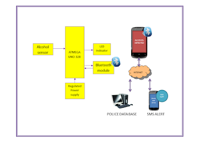
Alcohol Detection Smart android DIY KIT


OVERVIEW:

In recent years, it has become a fantasy that the people put their lives in risk. More often, the people consume alcoholic drinks and drive the vehicles. There are more chances that the person can hit the vehicle to any obstacle approaching him in the opposite direction due to unconsciousness caused by drinking. Hence, we make a modest attempt to design and develop a simple, low cost alcohol detection android application using an independent microcontroller.
The main aim of this project is to design a system that can identify whether the person, driving the vehicle, is in complete conscious state or not. The designed and developed system is installed in the module confining microcontroller, alcohol sensor and Bluetooth module.


WORKING:

From the above block diagram,
If the driver is drunk, the alcohol sensor fixed to the microcontroller will identify the alcohol content and its output will be triggered. This output of the sensor will be sent as an input to the microcontroller. Thus, the microcontroller continuously sends real time sensed alcohol detected values to the Bluetooth application where police is using at the scene, now android application analyses the streaming sensor values and display the level of alcohol detected.
If the alcohol level is above the normal range then it displays the detected level along with corresponding violated due amount and also sends those information to the police data base and in turn violation due amount will be placed via SMS to the driver.

COMPONENTS REQUIRED:

  • ATMEGA UNO 328.
  • Bluetooth shield
  • Alcohol sensor.
  • Jumper wires
  • Screw shield.
  • Android application

Friday 9 October 2015

RFID Reader-TTL


OVERVIEW:

This is a low frequency (125Khz) RFID Reader With TTL Output with range upto 15cms. The RFID Reader  is designed specifically for low-frequency (125 kHz) passive tags.Frequency refers to the size of the radio waves used to communicate between the RFID system components.

RFID Reader - TTL Features:


  • Low-cost method for reading passive RFID tags.
  • Built in Antenna
  • On-Board Power LED
  • Current Requirement <120mA
  • Communication TTL at 9600 baud.
  • Detecting Range upto 0-15cms.
  • High quality PCB FR4 Grade with FPT Certified. 
RFID Reader - TTL  Applicatons:
  • Rfid based attendance system
  • Rfid based smart shopping system 
  • Rfid based medical file tracking system 
  • Rfid based inventory management system
  • Rfid based access control system -security 
  • Rfid based library management system 
  • Rfid based security guard monitoring system
  • Rfid based asset tracking system ,
  • Rfid based vehicle parking system
  • Rfid based toll gate collection system
  • Rfid hotel room access control system .
  • Rfid based product identification for blind
  • Rfid based blind indoor navigation system.
  • Rfid based dual authentication system for software application ,
  • Rfid based industry supply chain control system
  • Rfid based smart conveyor
FOR MORE SCHEMATIC AND SAMPLES CODES: CLICK HERE


Thursday 8 October 2015

Bread Board Power Supply

OVERVIEW:

The breadboard power supply kit that takes power from a DC adapter jack  and provide outputs a selectable 1.8V,3.3V,5V,9V,12V and custom adjustable voltage from 0V to 12V.  Breadboard power supply headers are mounted on the bottom of the PCB for simple insertion into a breadboard.


PRODUCT FEATURES:


  • 1.8V,3.3V,5V,9V,12V regulated voltage.
  • Dual lane output.
  • Dual power port input.
  • Custom linear adjustable voltage from 0V to 12V.
  • Dual regulated power supply.
  • USB option for connecting Raspberry Pi and USB driven board 5V up to 1A.
  • Special designed for Breadboard usage.
For More Information: CLICK HERE


Saturday 5 September 2015

Smart Home Using Matlab GUI


OVERVIEW:

The popularity of home automation has been increasing greatly in recent years due to much higher affordability and simplicity through smartphone and computer connectivity. Home automation may include centralized control of lighting, HVAC (heating, ventilation and air conditioning), appliances, security locks of gates and doors and other systems, to provide improved convenience, comfort, energy efficiency and security. 


 Smart Home Using Matlab GUI Block Diagram:


Smart Home Using Matlab GUI Working Principle:


The microcontroller/processor is used to monitor and control the devices. An embedded c program is pre written into the microcontroller/processor which is programmed according to our need. The microcontroller/processor is then interfaced with the relays and the necessary water level sensors. Matlab will send a serial data to the microcontroller/processor via the serial interface.The microcontroller/processor replies if necessary and does the task assigned to it. The part of Matlab GUI is solely to provide user interface which when interrupted sends data to microcontroller/processor.

For More Details:


Controller:


  • Atmel (8051/89c52)/ PIC

Smart Home Using Matlab GUI Software Requirements:


  • MATLAB 2008 and above
  • LANGUAGE-Embedded C.
  • TOOLS: mikroC PRO for PIC/KEIL

Smart Home Using Matlab GUI Kits Contains:


  • PCB and programmed Microcontroller/Processor
  • Water Level Sensors (3)
  • 4 Relay Board
  • 1 Relay Board
  • USB to TTL converter
  • transformer (12 volts)
  • CD/DVD Project Report &CBT(Computer Based Training)*
  • Source code and datasheets
Reference :

Above design based on latest IEEE, Spring and other  international journal and Publication .The reference paper will be given along with kits.

Smart Home Using Matlab GUI Kits Details:

PIC Controller  

4 Relay  


Miscellaneous.

Friday 4 September 2015

LAN Based RFID Reader

OVERVIEW:

Ethernet RFID Reader is based on TCP/IP, can read RFID cards.This readers can easily connect to network.Installation is very easy. 


RFID Reader Features:


  • Low-cost method for reading passive RFID tags.
  • Built in Antenna
  • On-Board Power LED
  • Current Requirement <120mA
  • Detecting Range 5-15cms.
  • High quality PCB FR4 Grade with FPT Certified. 

RFID Reader - Applicatons:

  • RFID Remote/Web based attendance system
  • RFID Remote/Web based smart shopping system 
  • RFID Remote/Web based medical file tracking system 
  • RFID Remote/Web based inventory management system
  • RFID Remote/Web based access control system -security 
  • RFID Remote/Web based library management system 
  • RFID Remote/Web based security guard monitoring system
  • RFID Remote/Web based asset tracking system ,
  • RFID Remote/Web based vehicle parking system
  • RFID Remote/Web based toll gate collection system
  • RFID Remote/Web based hotel room access control system .
  • RFID Remote/Web based product identification for blind
  • RFID Remote/Web based blind indoor navigation system.
  • RFID Remote/Web based dual authentication system for software application ,
  • RFID Remote/Web based industry supply chain control system
  • RFID Remote/Web based smart conveyor

Ethernet Shield W5100 for Arduino:


  • With this Ethernet Shield, your Arduino board can be used to connect to internet.
  • Can be used as server or client.
  • Directly plug puzzle board, no soldering required.
  • Controller: W5100.
  • This is the latest version of the Ethernet Shield.
  • This Arduino Ethernet Shield which is based on the Wiznet W5100 Ethernet Chip gives you an easy way to get your Arduino Online.
  • It is directly supported by Arduino official Ethernet Library.
  • It adds a micro-SD card slot, which can be used to store files for serving over the network.
  • It is compatible with the Arduino Duemilanove (168 or 328), Uno as well as Mega (1280/2560) and can be accessed using the SD library.
  • The Wiznet W5100 provides a network (IP) stack capable of both TCP and UDP.
  • It supports up to four simultaneous socket connections.
  • Use the Ethernet library to write sketches which connect to the internet using the shield.
  • Fits all version of Arduino Main board,2009,UNO, mega 1280, mega 2560.
  • Size: 7cm x 5.4cm x 2.4cm - 2.76inch x 2.12inch x 0.94inch.
  • MAC address: 0xDE, 0xAD, 0xBE, 0xEF, 0xFE, 0xED byte mac[] = { 0xDE, 0xAD, 0xBE, 0xEF, 0xFE, 0xED }
Mega 2560 R3 ATmega2560-16AU Board Features:


  • Microcontroller:ATmega2560
  • Operating Voltage: 5V
  • Input Voltage (recommended):7-12V
  • Input Voltage (limits):6-20V
  • Digital I/O Pins: 54 (of which 14 provide PWM output)
  • Analog Input Pins:16
  • DC Current per I/O Pin:40 mA
  • DC Current for 3.3V Pin: 50 mA
  • Flash Memory:256 KB of which 4 KB used by bootloader
  • SRAM:8 KB
  • EEPROM:4 KB

LAN Based RFID Reader Block Diagram:


LAN Based RFID Reader Connection Diagram:


LAN Based RFID Reader Screenshot:


LAN Based RFID Reader Sample SDK Screenshot:


LAN Based RFID Reader Sample C# SDK Screenshot:


For More codes and software: Click Here