The prime functionality of alerting system is monitoring and quick detection of issues. Downtime is one of the dreaded terms and it occurs when the system is subjected to partial or full loss of availability thereby resulting in a loss. Loss could be in any form, revenue, time, output.
A comprehensive monitoring system that allows timely identification of issues proves to be indispensable. Also, it is important that a monitoring system allows operators to drill down from high level to granular level information so that those specific points can be used for root cause analysis
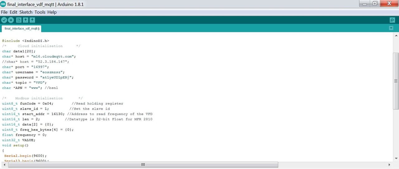
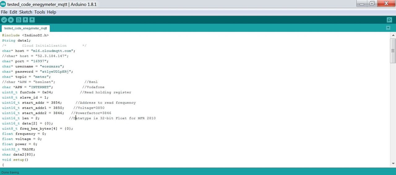
- Step 1 , Copy the code and configure the parameter as required by you
Step 2 - Execute the code
sample SMS Alert Code for your Reference
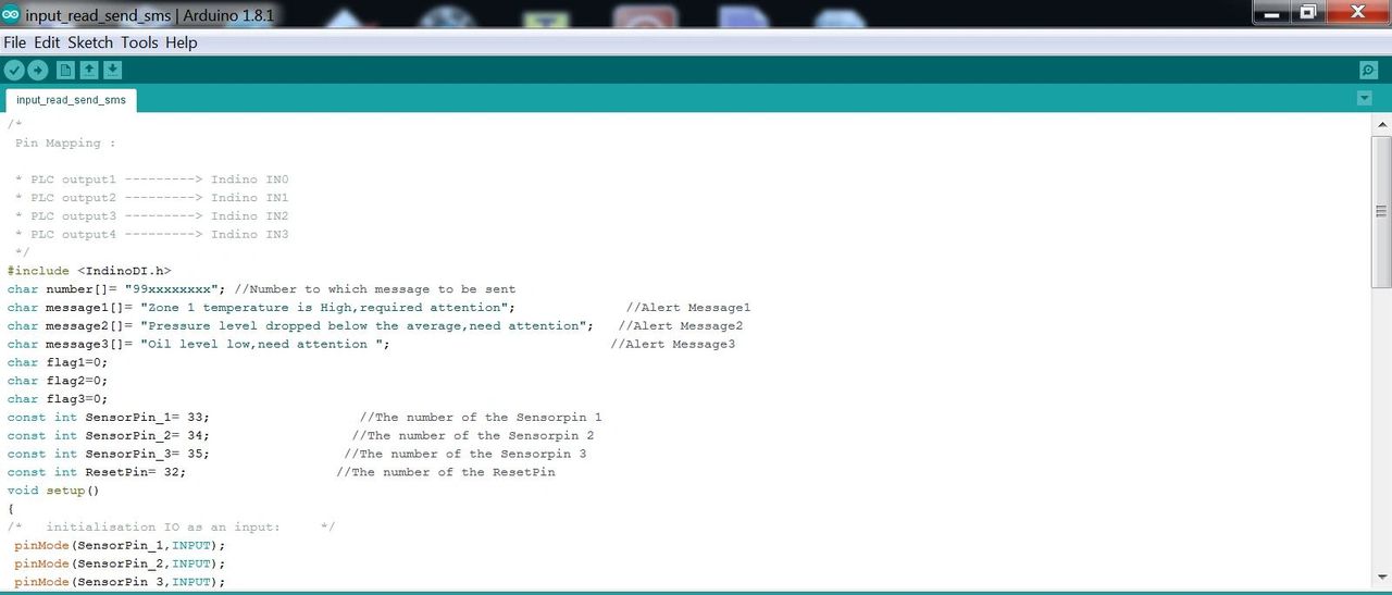
/*
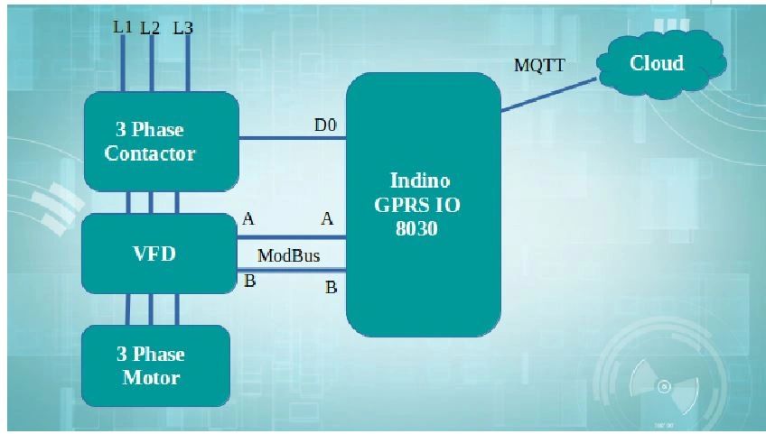
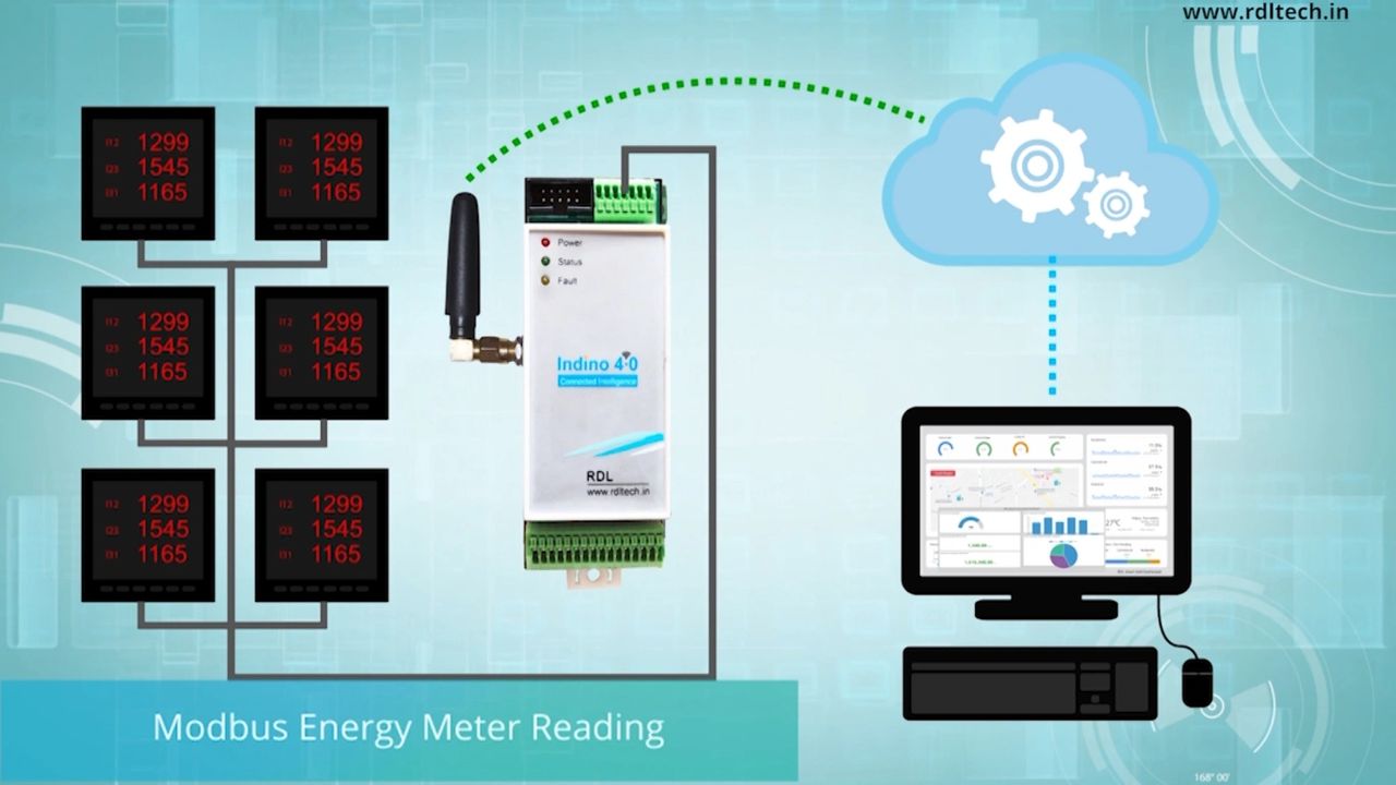
Pin Mapping :
* PLC output1 ---------> Indino IN0
* PLC output2 ---------> Indino IN1
* PLC output3 ---------> Indino IN2
* PLC output4 ---------> Indino IN3
*/
#include <IndinoDI.h>
char number[]= "94xxxxxxxx"; //Number to which message to be sent
char message1[]= "Zone 1 temperature is High,required attention"; //Alert Message1
char message2[]= "Pressure level dropped below the average,need attention"; //Alert Message2
char message3[]= "Oil level low,need attention "; //Alert Message3
char flag1=0;
char flag2=0;
char flag3=0;
const int SensorPin_1= 33; //The number of the Sensor pin 1
const int SensorPin_2= 34; //The number of the Sensor pin 2
const int SensorPin_3= 35; //The number of the Sensor pin 3
const int ResetPin= 32; //The number of the ResetPin
void setup()
{
/* initialisation IO as an input: */
pinMode(SensorPin_1,INPUT);
pinMode(SensorPin_2,INPUT);
pinMode(SensorPin_3,INPUT);
pinMode(ResetPin,INPUT);
Serial.begin(9600);
}
void loop()
{
if (digitalRead(SensorPin_1)==HIGH) //Check for alert input high
{
if(flag1==0) //Send the message only if flag is reset
{
Indino_GSM_Send_SMS(number, message1); //Command to send SMS
Serial.print(message1);
flag1=1; //Flag set to send the message
delay(5000); //Delay call 5sec to send message only once
}
}
if (digitalRead(SensorPin_2)==HIGH) sample SMS Alert Code for your Reference
{
if(flag2==0)
{
Indino_GSM_Send_SMS(number, message2);
Serial.print(message2);
flag2=1;
delay(5000);
}
}
if (digitalRead(SensorPin_3)==HIGH)
{
if(flag3==0)
{
Indino_GSM_Send_SMS(number, message3);
Serial.print(message3);
flag3=1;
delay(5000);
}
}
if (digitalRead(ResetPin)==HIGH) //Check for Reset to reset the device
{
flag1=0;
flag2=0;
flag3=0;
}
}
For more details visit https://rdltech.in/indino-4-0/f/automated-machine-fault-alerting-system