
Xbee Series 2 Point To Point Communication
XBee is very easy and popular wireless device. It is a transceiver, it can transmit data wirelessly and it can also receive data wirelessly. There are several types of XBee module and it might be confusing. The very popular XBee is Series 1 (802.15.4), comes with the firmware to create connection for point to point or star network. But bear in mind, many people actually thought it is using ZigBee protocol, but it is not compliance to ZigBee because it uses the low layer of ZigBee protocol only. Therefore XBee Series 1 (S1) cannot communicate with ZigBee device in the market. Anyway I don think many care because they just want to communicate among XBee, or wanted to have simple wireless communication. The XBee or XBee PRO is basically the same protocol, just PRO module have better transmit power and better receiver sensitivity. So I will be talking about XBee only, not the PRO. XBee Series 2 (ZB) does not offer any 802.15.4-only firmware; it is always running ZigBee mesh firmware. It is the new XBee module that we are carrying now. XBee S2 have better performance when you talk about mesh networking where it involve quite a lot of nodes: Coordinators, Routers and End Devices. You can read the datasheet if you want to, but I am going to talk about point to point only, Bear in mind, XBee S2 cannot communicate with XBee S1, it is not compatible in term of wireless communication.

Working
Assuming you have done installing USB driver and X-CTU, and the USB of SKXBee is plug in properly, you should see the POWER LED on SKXBee ON. There are two XBee S2 modules needed to be setup. I will show the 1st XBee S2 module setup, which I named it Coordinator 1. 2nd XBee S2 module will be Router 1.
Coordinator
You can choose either one of the XBee S2 to configure as coordinator. At the end, the host do not know which is which as XBee will become transparent once it is setup correctly.
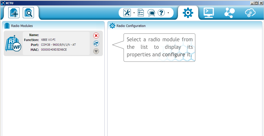
Launch X-CTU

Choose the COM Port, normally is the largest number. Easily you will see it because it is label as USB Serial Port (COM X). In this example is COM10. Your COM port might be different than mine, just choose those that being label as USB Serial port and click “Test/Query”.

If the baudrate and COM port number is correct, the X-CTU will display simple information such as modem type, firmware version and serial number. If there is no response, choose the other COM port and ensure the baudrate is 9600 (default).

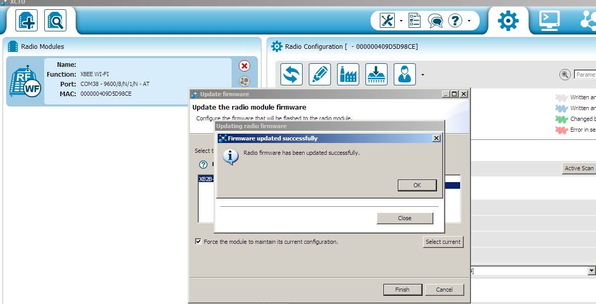
Proceed to the right tab on X-CTU, Modem Configuration. Click “Always Update Firmware” and click “Read” to grab data from XBee S2 module. Choose “ZIGBEE COORDINATOR AT” under Function Set, Set a preferable PAN ID, I simply set “1234”. You can also set the Node ID, I set “COORDINATOR1” as node ID, this is not critical. Record the SH and SL ID on this XBee S2 module, you will need it to set Router module. In my case, the SH is 13A200, SL is408C1470. This is Coordinator Source Address. Click “Write” and X-CTU will start loading the parameter you just set.

It will take around 30 seconds to 1 minute to complete the loading.

We will need to configure Coordinator again when you get the SH and SL of router . For the time being, we are done for Coordinator. You can close X-CTU now.
Router
If you have another SKXBee, connect it to your computer with another XBee S2 plug in. I will be using the same SKXBee, so I actually exchange the XBee 2S on it.
Launch X-CTU
Choose the COM Port, should be different number than the earlier SKXBee. Your COM port might be different than mine, just choose those that being label as USB Serial port and click “Test/Query”.

If the baudrate and COM port number is correct, the X-CTU will display simple information such as modem type, firmware version and serial number. If there is no response, choose the other COM port and ensure the baudrate is 9600 (default). Proceed to the right tab on X-CTU, Modem Configuration. Click “Always Update Firmware” and click “Read” to grab data from XBee S2 module.

Choose “ZIGBEE ROUTER AT” under Function Set, Set a preferable PAN ID, I simply set “1234”. You can also set the Node ID, I set “ROUTER1” as node ID. This is not critical. Record the SH and SL ID on this XBee S2 module, you will need it to set Coordinator module. In my case, the SH is 13A200, SL is4086A429. Key in the DH and DL address using the SH and SL from Coordinator module. My case is DH: 13A200, DL: 408C1470. Click “Write” and X-CTU will start loading the parameter you just set. It will take around 30 seconds to 1 minute to complete the loading. OK, we are done with Router module. If you like to check, you can go to Terminal tab and key in this command.
 Typing “+++” will ask XBee module to enter command mode and will response with “OK”. ATVR request for firmware version, and XBee will reply, my is 22A7 ATID request for PAN ID ATNI request for Node ID, which is ROUTER1 that I just set ATDL request for Destination Low Address ATSL request for Source Low Address ATCN force XBee module to exit command mode. Is fine if you don enter ATCN, after 5 seconds if there is no UART activity, XBee module automatic exit
command mode
Again, Coordinator Do not forget, we need to set the DH and DL on Coordinator XBee S2 module. Again, plug in Coordinator XBee S2 module, open X-CTU, read the information, and set the DH and DL that you grab from router’s SH and SL. Click write to load the parameters into XBee module.

Done OK, now both this XBee S2 modules are setup and linked together, once they are powered, they are paired. sending data via UART to one of the XBee module will automatically being transmitted wirelessly to the other XBee module and further transmit out from the UART, and this apply for both way. Here I have install two SKXBee with Coordinator and Router that we setup. Connected to COM10 and COM25.
 If you notice, the DL and SL is paired up. I enter command mode to grab the information we configured and exit the command mode with ATCN. the following text after ATCN and OK is actually happening in transparent mode. The text you type in Router1 XBee will transmit to Coordinator1 XBee and display on terminal and vise versa. Now, you can use this pair of XBee S2 as wireless point to point communication. It has become same as the XBee S1 if you configure the DL and SL correctly.
XBee is very easy and popular wireless device. It is a transceiver, it can transmit data wirelessly and it can also receive data wirelessly. There are several types of XBee module and it might be confusing. The very popular XBee is Series 1 (802.15.4), comes with the firmware to create connection for point to point or star network. But bear in mind, many people actually thought it is using ZigBee protocol, but it is not compliance to ZigBee because it uses the low layer of ZigBee protocol only. Therefore XBee Series 1 (S1) cannot communicate with ZigBee device in the market. Anyway I don think many care because they just want to communicate among XBee, or wanted to have simple wireless communication. The XBee or XBee PRO is basically the same protocol, just PRO module have better transmit power and better receiver sensitivity. So I will be talking about XBee only, not the PRO. XBee Series 2 (ZB) does not offer any 802.15.4-only firmware; it is always running ZigBee mesh firmware. It is the new XBee module that we are carrying now. XBee S2 have better performance when you talk about mesh networking where it involve quite a lot of nodes: Coordinators, Routers and End Devices. You can read the datasheet if you want to, but I am going to talk about point to point only, Bear in mind, XBee S2 cannot communicate with XBee S1, it is not compatible in term of wireless communication.

Working
Assuming you have done installing USB driver and X-CTU, and the USB of SKXBee is plug in properly, you should see the POWER LED on SKXBee ON. There are two XBee S2 modules needed to be setup. I will show the 1st XBee S2 module setup, which I named it Coordinator 1. 2nd XBee S2 module will be Router 1.
Coordinator
You can choose either one of the XBee S2 to configure as coordinator. At the end, the host do not know which is which as XBee will become transparent once it is setup correctly.
Launch X-CTU

Choose the COM Port, normally is the largest number. Easily you will see it because it is label as USB Serial Port (COM X). In this example is COM10. Your COM port might be different than mine, just choose those that being label as USB Serial port and click “Test/Query”.

If the baudrate and COM port number is correct, the X-CTU will display simple information such as modem type, firmware version and serial number. If there is no response, choose the other COM port and ensure the baudrate is 9600 (default).

Proceed to the right tab on X-CTU, Modem Configuration. Click “Always Update Firmware” and click “Read” to grab data from XBee S2 module. Choose “ZIGBEE COORDINATOR AT” under Function Set, Set a preferable PAN ID, I simply set “1234”. You can also set the Node ID, I set “COORDINATOR1” as node ID, this is not critical. Record the SH and SL ID on this XBee S2 module, you will need it to set Router module. In my case, the SH is 13A200, SL is408C1470. This is Coordinator Source Address. Click “Write” and X-CTU will start loading the parameter you just set.

It will take around 30 seconds to 1 minute to complete the loading.

We will need to configure Coordinator again when you get the SH and SL of router . For the time being, we are done for Coordinator. You can close X-CTU now.
Router
If you have another SKXBee, connect it to your computer with another XBee S2 plug in. I will be using the same SKXBee, so I actually exchange the XBee 2S on it.
Launch X-CTU
Choose the COM Port, should be different number than the earlier SKXBee. Your COM port might be different than mine, just choose those that being label as USB Serial port and click “Test/Query”.


Choose “ZIGBEE ROUTER AT” under Function Set, Set a preferable PAN ID, I simply set “1234”. You can also set the Node ID, I set “ROUTER1” as node ID. This is not critical. Record the SH and SL ID on this XBee S2 module, you will need it to set Coordinator module. In my case, the SH is 13A200, SL is4086A429. Key in the DH and DL address using the SH and SL from Coordinator module. My case is DH: 13A200, DL: 408C1470. Click “Write” and X-CTU will start loading the parameter you just set. It will take around 30 seconds to 1 minute to complete the loading. OK, we are done with Router module. If you like to check, you can go to Terminal tab and key in this command.

command mode
Again, Coordinator Do not forget, we need to set the DH and DL on Coordinator XBee S2 module. Again, plug in Coordinator XBee S2 module, open X-CTU, read the information, and set the DH and DL that you grab from router’s SH and SL. Click write to load the parameters into XBee module.

Done OK, now both this XBee S2 modules are setup and linked together, once they are powered, they are paired. sending data via UART to one of the XBee module will automatically being transmitted wirelessly to the other XBee module and further transmit out from the UART, and this apply for both way. Here I have install two SKXBee with Coordinator and Router that we setup. Connected to COM10 and COM25.


