Start Your Embedded System Design Journey Today..!
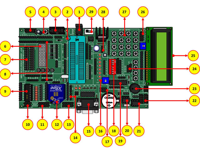
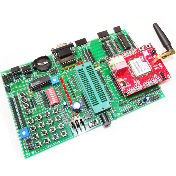
PIC essential development features a plug and play design that makes it easy for connections and helps Students, hobbyists, enthusiasts, and professionals to focus more on Program / application development. PIC Development Board Trainer kit equipped with on board IO’s, communication interfaces & peripherals. It is really easy to design, experiment with, and test circuits without soldering. It's used in many educational institutions and R&D LAB across the world.
ORDER CODE: RDL740
Features:
Plug & Play Interface Connectivity.
Professional EMI/RFI Complaint PCB Layout Design
Modular Block design makes Easy access & quick Prototyping
FRC connectivity features minimize the connection Error.
High Quality Grade PCB with wooden Enclosure.
8 interfacing LED’s.
1 * 4 Menu keypad.
4* 4 Matrix Keypad.
RS232, RS485, USB communication port.
7 Segment Multiplexed Display.
16*2 LCD & OLED Display
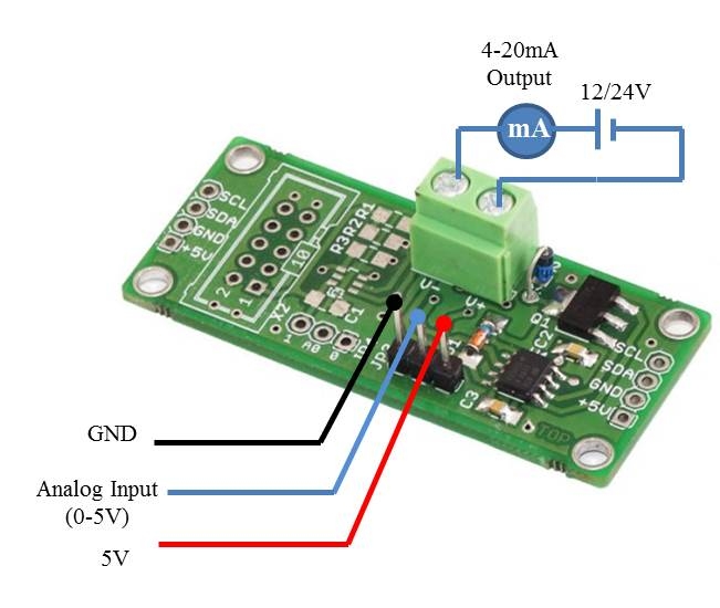
ADC & DAC Card.
8 bit 4 port IO.
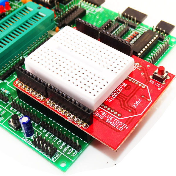
On Board WiFi / Bluetooth Connectivity
3.3 to 5V Level Converter.
Power Supply 3.3V and 5V
SD CARD Interface.
RTC & EEPROM Interface.
DC Motor/ Stepper Motor Driver.
Relay, Buzzer.
1xTemperature Sensor.
3x Analog Test POT.
MCU
Only 35 single-word instructions to learn
All single-cycle instructions except for program branches, which are two-cycle
Operating speed: DC – 20 MHz clock input DC – 200 ns instruction cycle
Up to 8K x 14 words of Flash Program Memory, Up to 368 x 8 bytes of Data Memory (RAM), Up to 256 x 8 bytes of EEPROM Data Memory
Pinout compatible to other 28-pin or 40/44- pin PIC16CXXX and PIC16FXXX microcontrollers
Analog Features
- 10-bit, up to 8-channel Analog-to- Digital Converter(A/D)
Peripheral Features
Timer0: 8-bit timer/counter with 8-bit prescaler
Timer1: 16-bit timer/counter with prescaler,
Timer2: 8-bit timer/counter with 8-bit period register,prescaler and postscaler
Two Capture, Compare, PWMmodules
Synchronous Serial Port (SSP) with SPI™ (Mastermode)and I2C™ (Master/Slave)
Universal Synchronous Asynchronous Receiver Transmitter(USART/SCI) with 9-bit address detection
Parallel Slave Port (PSP) – 8 bits wide with external RD,WR and CS controls (40/44-pin only)
Scope of Learning Experiments:
LED blinking.
8 bit LED Left shift, Right shift and counting operation.
Keypad Interrupt Interface
16*2 LCD interface.
Matrix Keypad Interface.
ADC& DAC interface.
Traffic Light Signal Interface.
8 bit DIP switch interface.
7 Segment interface.
L298 Driver for DC Motor and Stepper motor interface.
Elevator Interface.
Buzzer, Relay interface.
RS485, RS232 serial communication
PWM Interface
UART Operation
RTC DS1307I2C protocol interface.
AT24C04 EEPROM I2C protocol interface.
RF/WiFiCommunication.
SPI protocol interface
Temperature Sensor Interface.
Supported IC:
Package Contains :
- Development Board with Wooden Enclosure
- USB Cable.
- 12V 2A Adapter.
- FRC Cable
Documents:
- Datasheet (PIC Development Board)