Pages

Monday 30 June 2014

Xbee Development Board with Voltage Regulator and Level Converter Compatible for Arduino

Quick Overview

Arduino Xbee Adapter Development Board allows an Arduino board to communicate wirelessly using  Zigbee or BlueTooth.This shield is build up by two parts: Bluetooth and Xbee shield.This Bluetooth shield is a serial port Bluetooth module (Slave/Master) breakout board. you can directly stack on Arduino and use the UART port for Bluetooth communication.XBee Shield is an enhanced Zigbee XBee Series modules breakout board for Arduino, it can directly plug in with Arduino, and use any pin of the basic board to connect with the XBee module serial port.XBee Shield with Logic Level Converter is an enhanced serial port XBee module breakout board.It can directly plug in with Arduino.


 Xbee Development Board with Voltage Regulator and Level Converter Compatible for Arduino


Features:
  • Compatible with all Arduinos.
  • Can be use as XBEE development board.
  • Mounts directly onto your Arduinos.
  • Reset button brought out.
  • With Logic Level Converter (3.3V to 5V ).
  • Stackable interfaces.
For more details please Click Here

Xbee USB Adapter with FT232RL

Quick Overview

Xbee USB Adapter with FT232RL  shield works with all XBee modules including the Series 1 and Series 2.5, standard and Pro version.Plug the unit into the XBee shield, attach a mini USB cable, and you will have direct access to the serial and programming pins on the XBee unit.

Xbee USB Adapter with FT232RL

Features:
  • 3.3V and 5V dual power output
  • 3.3V and 5V IO compatible
  • USB 2.0 protocol
  • Needs no external crystal
  • UART interface support for 7 or 8 data bits, 1 or 2 stop bits and odd / even / mark / space / no parity
  • Power Supply USB 5V.
  • Single chip USB to asynchronous serial data transfer interface.
  • Data transfer rates from 300 baud to 3 Mbaud (RS422, RS485, RS232 ) at TTL levels.
  • UART interface support for 7 or 8 data bits, 1 or 2 stop bits and odd / even / mark / space / no parity.
  • Integrated +3.3V level converter for USB I/O.
  • True 5V/3.3V/2.8V/1.8V CMOS drive output and TTL input.

Driver Tutorial

 For Download Click Here

For more Please Click Here


L298N Motor Drive Shield

Quick Overview

L298N is a high voltage, high current motor driver chip, with the highest working voltage of 46V, continuous operating current of 2A, and instantaneous peak current up to 3A. The chip contains two "H bridges" which are high-voltage and high current full-bridge drivers that can directly drive two DC motors.

L298N Motor Drive Shield  


Features:
  • Driver: L298N Dual H Bridge DC Motor Driver IC
  • Motor Power Supply Vs: +5 V to +35 V
  • Max average current 2A
  • peak current Io: 3A
  • Logic Level Power Vss: +5 V ~ +7 V (Onboard 5V Regulator can be used if Motor Power is > 7.0V)
  • Logic level power: 0 ~ 36mA
  • Two motor direction indicator LEDs.
  • Screw-terminals for power and motor connections.
Sample codes:
//Program 1: PWM Speed Control 
int E1 = 9; 
int M1 = 4; 
int E2 = 10; 
int M2 = 5; 
 
void setup() 
 pinMode(M1, OUTPUT); 
 pinMode(M2, OUTPUT); 
 
void loop() 
 int value; 
 for(value = 0 ; value <= 255; value+=5) 
 { 
 digitalWrite(M1,HIGH); 
 digitalWrite(M2, HIGH); 
 analogWrite(E1, value); //PWM Speed Control 
 analogWrite(E2, value); //PWM Speed Control 
 delay(100); 
 } 
 
//Program 2: Motor Direction control
int ENA=9; //Connect on Pin 9
int IN1=4; //Connect on Pin 4
int IN2=5; //Connect on  Pin 5
int ENB=10; //Connect on Pin 10
int IN3=6; //Connect on  Pin 6
int IN4=7; //Connect on  Pin 7
 
void setup() {
 pinMode(ENA,OUTPUT);
 pinMode(ENB,OUTPUT);
 pinMode(IN1,OUTPUT);
 pinMode(IN2,OUTPUT);
 pinMode(IN3,OUTPUT);
 pinMode(IN4,OUTPUT);
 digitalWrite(ENA,HIGH);// Activate motor A
 digitalWrite(ENB,HIGH);// Activatemotor B
}
void loop(){
 
 digitalWrite(IN1,LOW);
 digitalWrite(IN2,HIGH);
 digitalWrite(IN3,HIGH);
 digitalWrite(IN4,LOW);
 delay(1000);
 digitalWrite(IN1,LOW);
 digitalWrite(IN2,HIGH);
 digitalWrite(IN3,LOW);
 digitalWrite(IN4,HIGH);
 delay(1000);
 digitalWrite(IN1,HIGH);
 digitalWrite(IN2,LOW);
 digitalWrite(IN3,LOW);
 digitalWrite(IN4,HIGH);
 delay(1000);
 digitalWrite(IN1,HIGH);
 digitalWrite(IN2,LOW);
 digitalWrite(IN3,HIGH);
 digitalWrite(IN4,LOW);
 delay(1000);
}

For more details Click Here 

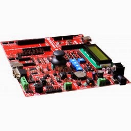
Discovery Board V1.0

Quick Overview

Discovery board is a full-featured universal development environment for different microcontroller architectures. Board is equipped with many on-board modules which give you great power and flexibility when creating or testing your prototype. The board is designed with inbuilt arduino USB shield with several numbers of shields provided and the microcontroller boards are also specifically designed as per the requirement of the board. This board is one of the latest innovations in the domain of Electronics and Communication by the pioneers in technology, ISOFT Technologies. The board is designed in compliance with the latest industrial standards facilitating feature rich options implemented using the I2C, SPI, RS485, UART, and CAN protocol. The main advantage of this board is Simplicity in programing and also compliments the existing Microcontroller boards as a daughter board to enhance the functionalities. This board supports ADC, PWM, LCD, RTC, EEPROM, 4x4 Keypad Matrix, JOYSTICK, XBEE, Level converter, MMC/SD card connector, Arduino USB shield with inbuilt function to ease programming. Discovery Board maintains product excellence and performance by introducing innovative, cost effective solutions to cater the needs of students who dream to innovate and excel in the field of Electronics and Engineering, thus supporting an array of domains in real time, providing solutions you can count on. 

Discovery Board V1.0


Features:
1.  Power supply module
2.  I2C protocol module
3.  USB/UART/TTL module
4.  RS485 protocol module
5.  LCD2x16 display contrast potentiometer
6.  RTC module
7.  Univarsal Bus socket
8.  CAN protocol module
9.  Switches
10. LED Outputs
11. 4x4 Keypad Matrix module
12. 5 Position JOYSTICK
13. Level Convertor
14. ADC module
15. Piezo buzzer
16. RDUINO bus
17. Potentiometer to set ADC and PWM values
18. XBEE Adaptor module
19. MMC/SD card connector
20. SPI bus

Kit includes
  • RDL Discovery Board V1.0
For more details Click Here


Bluetooth Development Board Compatible for Arduino

Quick Overview

This Bluetooth shield is a serial port Bluetooth module (Slave/Master) breakout board. you can directly stack on Arduino and use the UART port for Bluetooth communication.

Bluetooth Development Board Compatible for Arduino 

Features:
  • The BT Shield integrates a HC-06 Serial Bluetooth module
  • It can be easily used with Arduino for transparent wireless serial communication.
  • Default baud rate: 9600, data bits: 8, stop bit: 1, Parity: No parity
  • Default PINCODE:”1234”
  • Operation Level: Digital 3.3V-5V
 For more details  Click Here


FRIENDLY ARM 9 MINI 2440 WITH 3.5'' LCD

Quick Overview

FriendlyARM Mini 2440 SBC (Single-Board Computer) with 400 MHz Samsung S3C2440 ARM9 processor. The board measures 10 cm x 10 cm, ideal for learning about ARM systems. 

FRIENDLY ARM 9 MINI 2440 WITH 3.5'' LCD


Specification

  • Dimension: 100 x 100 mm
  • CPU: 400 MHz Samsung S3C2440A ARM920T (max freq. 533 MHz)
  • RAM: 64 MB SDRAM, 32 bit Bus
  • Flash: 64 MB / 128 MB / 256 MB / 1GB NAND Flash and 2 MB NOR Flash with BIOS
  • EEPROM: 1024 Byte (I2C)
  • Ext. Memory: SD-Card socket
  • Serial Ports: 1x DB9 connector (RS232), total: 3x serial port connectors
  • USB: 1x USB-A Host 1.1, 1x USB-B Device 1.1
  • Audio Output: 3.5 mm stereo jack
  • Audio Input: Connector + Condenser microphone
  • Ethernet: RJ-45 10/100M (DM9000)
  • RTC: Real Time Clock with battery
  • Beeper: PWM buzzer
  • Camera: 20 pin Camera interface (2.0 mm)
  • LCD Interface
    • STN Displays
    • TFT Displays
    • 41 pin connector for FriendlyARM Displays (3.5" and 7") and VGA Board
  • Touch Panel: 4 wire resistive
  • User Inputs: 6x push buttons and 1x A/D pot
  • User Outputs: 4x LEDs
  • Expansion: 40 pin System Bus, 34 pin GPIO, 10 pin Buttons (2.0 mm)
  • Debug: 10 pin JTAG (2.0 mm)
  • Power: regulated 5V (DC-Plug: 1.35mm inner x 3.5mm outer diameter)
  • Power Consumption: Mini2440: 0.3 A, Mini2440 + 3.5" LCD: 0.6 A, Mini2440 + 7" LCD: 1 A
  • OS Support
    • Windows CE 5 and 6
    • Linux 2.6
    • Android 
For more details Click Here


Sunday 29 June 2014

Joystick Shield

Quick Overview

The Joystick Shield easily stacks on top of your ATmega 328 R3 and turns it into a simple robotic and gaming controller. Six momentary push buttons (4+2), a two-axis thumb joystick and optional remote transmission adapter for Xbee and Bluetooth allows your ATmega 328 R3 to control from remote location.
                        ATmega 328 R3 digital pins D3-D8 are connected to momentary push buttons, when pressed they will pull the pin HIGH. Voltage accross analog pin 0 varies proportionally for the vertical movement of the joystick, likwise horizontal movement can be tracked at analog pin 1.Xbee Dout is connected to D0(Rx) and Din is connected to D1(Tx) of ATmega 328 R3 sheild.

Joystick Shield

Features:
  • Jumbo yellow 4 keypad.
  • Joystick.
  • Two selection switch.
  • RoHS compliant.
  • Compatible with UNO R3 and Mega 2560.

For more details Click Here


Wireless Xbee Data Logger Sheild Compatible for Arduino

Quick Overview

The data logger is a reliable, well-rounded and versatile design. Can log wireless data throgh Xbee easily. Can be used for saving data to files on any FAT16 or FAT32 formatted SD card, to be read by any plotting, spreadsheet or analysis program. The included Real Time Clock timestamps all your data with the current time, so that you know precisely what happened when.The Wireless SD Shield provides a regulated Digi Xbee slot which makes the wireless connective easier. Meanwhile a microSD slot gives it the capability to store the data in real time.

Wireless Xbee Data Logger Sheild Compatible for Arduino

Features:

  • SD card interface works with FAT16 or FAT32 formatted cards. 3.3v level shifter circuitry prevents damage to your SD card.
  • Real time clock (RTC) keeps the time going even when the Arduino is unplugged. The battery backup lasts for years.
  • 3.3V voltage level converter for memory card,  reliably runs SD cards that require a lot of power to run.
  • With Xbee included.

For More Details Click Here


GSM Modem- Arduino Compatible

Quick Overview:

GSM/GPRS Modem-RS232 is built with Dual Band GSM/GPRS engine- SIM900A, works on frequencies 900/ 1800 MHz. The Modem is coming with RS232 interface, which allows you connect PC as well as microcontroller with RS232 Chip(MAX232). The baud rate is configurable from 9600-115200 through AT command. The GSM/GPRS Modem is having internal TCP/IP stack to enable you to connect with internet via GPRS. It is suitable for SMS, Voice as well as DATA transfer application in M2M interface. The onboard Regulated Power supply allows you to connect wide range unregulated power supply . Using this modem,you can make audio calls, SMS, Read SMS, attend the incoming calls and internet ect through simple AT commands.

GSM Modem- Arduino Compatible


GSM Sim 900A Modem Features:

  • Dual-Band GSM/GPRS 900/ 1800 MHz
  •  RS232 interface for direct communication with computer or MCU kit
  •  Configurable baud rate
  • Power controlled using 29302WU IC.
  • ESD Compliance.
  • Enable with MIC and SPeaker socket.
  • With slid in SIM card tray.
  • With Stub antenna and SMA connector
  •  Input Voltage: 12V DC.
  • High quality PCB FR4 Grade with FPT Certified.

GSM Sim 900A Modem Applications:
  • Industrial automation.
  • GPRS based data logging.
  • GPRS and GPS application.
  • Home automation.
  • Health monitoring. 
  • Agriculture automation.
  • Vehicle tracking.
  • Remote monitoring and controlling.
  • GPRS based Weather report logging. 
  • GSM GPRS based Security alert. 
  • GPRS based remote terminal for file transfer.
  • IVRS.
  • Bulksms sending.

GSM Sim 900A Modem Schematic:


GSM Utility Software Features:

  • Bulk SMS sending
  • AT command testing terminal
  • Step by step GPRS setup.
  • Sample Codes


Screenshots:


For More Sample Codes & Schematic : CLICK HERE

GSM SIM 900A module with Stub Antenna and SMA connector

Quick Overview

GSM/GPRS Modem-RS232 is built with Dual Band GSM/GPRS engine- SIM900A, works on frequencies 900/ 1800 MHz. The Modem is coming with RS232 interface, which allows you connect PC as well as microcontroller with RS232 Chip(MAX232). The baud rate is configurable from 9600-115200 through AT command. The GSM/GPRS Modem is having internal TCP/IP stack to enable you to connect with internet via GPRS. It is suitable for SMS, Voice as well as DATA transfer application in M2M interface. The onboard Regulated Power supply allows you to connect wide range unregulated power supply . Using this modem,you can make audio calls, SMS, Read SMS, attend the incoming calls and internet ect through simple AT commands.
GSM SIM 900A module with Stub Antenna and SMA connector

Features:
  • Dual-Band GSM/GPRS 900/ 1800 MHz
  •  RS232 interface for direct communication with computer or MCU kit
  •  Configurable baud rate
  •  Stub Antenna and SMA Connector.
  •  SIM Card holder.
  •  Built in Network Status LED
  •  Inbuilt Powerful TCP/IP protocol stack for internet data transfer over GPRS.
  •  Input Voltage: 12V DC.
 For More Details Click Here