Pages

Monday, 25 April 2022


Industrial Data Logger 2G GPRS


The product is designed to seamlessly integrate with the IoT and Analytical processing systems. Supporting multiple I/O options, interfaces data logger is a perfect fit to build custom automation solutions. Industrial Data Logger 4.0 can used to build the custom industrial solution for monitoring and controlling PLC and SCADA, HMI, VFD Motors, servo, Valves, energy meter, actuators, relays, encoder, rfid and finger print readers, industrial sensors and many more with below mentioned operational benefits.

Operational Benefits:

Industrial Data Logger 4.0 can used to build the custom industrial solution for monitoring and controlling PLC and SCADA, HMI, VFD Motors, servo, Valves, energy meter, actuators, relays, encoder, rfid and finger print readers, industrial sensors and many more with below mentioned operational benefits.

  • Improved productivity & asset utilization.
  • Preventive maintenance.
  • Reduced downtime.
  • Paperless production environment.
  • Performance Forecasting.
  • Production count, rejections.

Features:

  • 12 x isolated Analog Input Channel 0-10V , 0-24v , 4-20mA.                                                                                      
  • 4x isolated Digital input 24V
  • 3x Isolated digital output / PWM 24v
  • 1x Relay ( NO & C)
  • 1x Isolated RS485 for MODBUS RTU communication
  • 1x Isolated Ethernet 10/100Mbps MODBUS TCP Communication
  • 1x USB-device interface for configuring, monitoring and download
  • 1x WiFi / 2G wireless communication
  • Configure and Read Multiple Slave IDs,Selectable Input Register Holding Register & Coil.
  • Configurable  Data type and Conversion method (INT ,Long INT , FLOAT , Double Float & RawHex)
  • Configurable Scaling factor enabling option for Analog channel .
  • Configurable WiFi / GPRS  Interface 
  • Configurable data transferring protocol JSON / MQTT and FTP
  • Support secure communication SSL
  • Custom Configurable polling interval
  • Custom Configurable 32 bit counter input
  • 8 GB inbuilt storage
  • Data Logs and stores its CSV file during network failure
  • Logger Sends offline data once Network and Server Connected
  • Configurable Live / Schedule upload offline data
  • Remote control / Activating Relay / Digital output
  • Configurable Alarm
  • OTA (Over The Air) Firmware upgrade for WiFi devices.
  • LED indicators to indicate Power, Network availability, status & Fault.
  • Auto Maintain socket / server  connection
  • Easy configurable connectivity for  cloud platform AWS / Azure / Google / Oracle / Things board.

FOR MORE INFO CLICK HERE

Friday, 22 April 2022


Cloud PLC 4.0


Cloud PLC 4.0 supporting for wide range of industrial protocols like Modbus, MQTT, JSON, RESTful, TCP/UDP, SNMP protocol, which makes the monitoring and solution integration, easier than ever for IT engineers through open source APIs. Cloud PLC 4.0 can used to build the custom industrial solution for monitoring and controlling PLC and SCADA, HMI, VFD, Motors, servo, Valves, energy meter,
actuators, relays, encoder, RFID and fingerprint readers, industrial sensors 

Features:

  • Lx6 Microprocessor 32 bit, with Clock Frequency 240MHz

  • 4 x Isolated Analog input 0-24V

  • 6x isolated Digital input 24V

  • 4x Isolated digital output / PWM 24V

  • 2x Relay ( NO & C)

  • 1x Isolated RS485

  • DS3231 RTC

  • 1x WiFi

  • UART Programming

  • OTA (Over The Air) Firmware upgrade for WiFi devices

  • 8 GB inbuilt storage

  • LED indicators to indicate Power

  Order Information Table:


      For more info : CLICK HERE                                       


Wednesday, 20 April 2022


                     Wi-Fi - 8 Channel Relay Board ESP32


RDL WiFi Eight Channel Relay Board is controlled through WiFi. The WiFi relay board is with 8 SPDT relays rated up to 7A each. You can control devices 230V / 120V (up to 8) directly with one such relay unit. Suitable for home automation applications, hobby projects, industrial automation.


Features:

  • 8 SPDT Relay channels (7A 250V,12A 120V,10A 125VAC, 10A 28VDC).

  • Power supply:12VDC 2AMP

  • Current consumption: 1A.

  • LED indication for relay & power supply.

  • Design based on highly proven IC ULN2803 as driver.

  • Node MCU Firmware updated.

  • High-quality PCB FR4 Grade with FPT Certified. 


ESP32 Features:

MCU 

  • ESP32-D0WD-V3 embedded, Xtensa® dual-core 32-bit LX6 microprocessor, up to 240 MHz 

  • 448 KB ROM for booting and core functions

  • 520 KB SRAM for data and instructions 

  • 16 KB SRAM in RTC

  • 4 MB SPI flash


Wi-Fi 

  • 802.11b/g/n 

  •  Bit rate: 802.11n up to 150 Mbps

  •  A-MPDU and A-MSDU aggregation 

  •  0.4 µs guard interval support

  •  Center frequency range of operating channel: 2412 ~ 2484 MH


Bluetooth® / BLE

  •   Bluetooth V4.2 BR/EDR and Bluetooth LE specification

  •  Class-1, class-2 and class-3 transmitter

  •  AFH

  •  CVSD and SBC


Security: 

  • WFA, WPA/WPA2 and WAP1   


Android Play store Screenshot:

 IP Adress:      192.168.4.1

 Port Number: 8080


Package Contains :

  • 8 Channel Relay Board + ESP32 + XBEE USB Adapter with FT232RL +  USB Cable
For more info: CLICK HERE


Monday, 18 April 2022


EXPERIMENT NO 7 

ADC 
Aim: 

To Interface ADC with ESP 32- Microcontroller Module. 

Description: 

To learn how to read ADC values using ESP32-Microcontroller. 

Hardware required: 

ESP32-Microcontroller Development board and FRC Cable.


Procedure:
 

1. Connect P1 port and SV12(ADC & Temp) port using FRC cable as shown above. 
2. Connect the USB cable to the board. 
3. Open Arduino IDE .Select DOIT ESP32 DEVKIT V1 in boards and select COM port. 
4. Write the program, verify and Upload it. 
5. Open the serial monitor to observe the output.


Program:

const int adc1=34;

const int adc2=35;

const int adc3=32;

int value1=0, value2=0, value3=0;

float res1=0, res2=0, res3=0;


void setup() {

  Serial.begin(115200);

  pinMode(adc1, INPUT);    // Pins Port1 Connected to ADC Knobs

  pinMode(adc2, INPUT);

  pinMode(adc3, INPUT);

  delay(500);


}


void loop() {

  delay(1000);

  value1=analogRead(adc1);

  value2=analogRead(adc2);

  value3=analogRead(adc3);


  res1=float((value1*3.3)/4095);   //3.3v is maximum voltage applied as a input

  res2=float((value2*3.3)/4095);   //it is 12bit ADC hence dividing by 4095 gives actual voltage

  res3=float((value3*3.3)/4095);


 Serial.print("The output of ADC1= ");

 Serial.print(res1);

 delay(500);


 Serial.print("\t The output of ADC2= ");

 Serial.print(res2);

 delay(500);


 Serial.print("\t The output of ADC3= ");

 Serial.println(res3);

 delay(500);

}


Wednesday, 13 April 2022

                                                              EXPERIMENT NO 6 

                                                             IR (Infrared) Sensor

Aim: 

To Interfacing IR sensor with ESP32-Microcontroller module

Description: 

To learn how to read values from an IR sensor using ESP32-Microcontroller

Hardware required: 

ESP32-Microcontroller Development board, IR sensor, F-F Patch Chords


Procedure: 

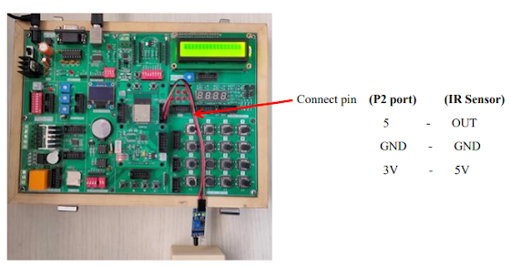
1. Connect P2 port pins (5, GND, 3V) to IR Sensor pins (OUT, GND, 5V) using patch chords as shown above. 

2. Connect the USB cable to the board. 

3. Open Arduino IDE .Select DOIT ESP32 DEVKIT V1 in boards and select COM port. 

4. Write the program, verify and Upload it.

5. Now you can see the output on the serial monitor.


Tuesday, 12 April 2022

                                                                EXPERIMENT NO 5 

                                                              Liquid Crystal Display


Aim: 

To interface LCD display with ESP32-Microcontroller module.


Description: 

To display the message on the LCD screen.


Hardware required: 

ESP32-Microcontroller Development board and FRC Cable


Procedure: 

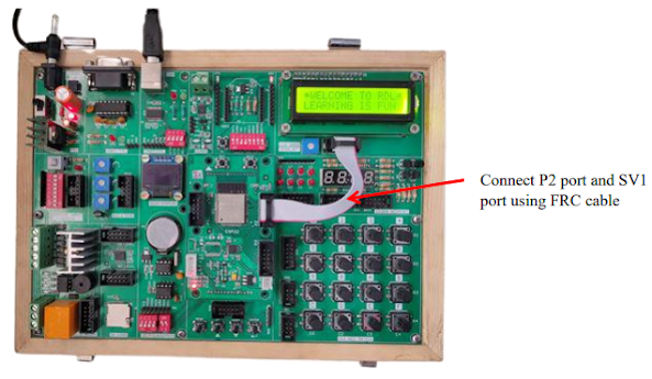
1. Connect P2 port and SV1(LCD 16*2 Display) port using FRC cable as shown above. 
2. Connect the USB cable to the board. 
3. Open Arduino IDE .Select DOIT ESP32 DEVKIT V1in boards and select COM port. 
4. Write the program, verify and Upload it. 5. Now you can see the output on LCD.


Wednesday, 6 April 2022

Hex Keypad

                                                                EXPERIMENT NO 4 

                                  Hex Keypad 

Aim: 

To interface 4x4 Hex Keypad with ESP32-Microcontroller module.

Description: 

To display the pressed key on the serial monitor. 

Hardware Required: 

ESP32-Microcontroller Development board and FRC Cable   


Procedure: 

1. Connect P2 port and SV5(4*4 Key Matrix) port using FRC cable as shown above. 

2. Connect the USB cable to the board. 

3. Open Arduino IDE .Select DOIT ESP32 DEVKIT V1 in boards and select COM port. 

4. Now Write the program, verify and Upload it. 

5. After uploading is done open serial monitor to observe the output. 

6. On your serial monitor, the number appears for each switch pressed.