Pages

Monday, 11 October 2021

LiFi


LiFi Visible Light Communication Compatible for Raspberry Pi


RPI Li-Fi Shield is a plug-and-play evaluation board for developing a wide array of visible light communication applications in consumer, wearable, industrial, medical and Internet of Things (IoT). RPI Li-Fi Shield transfers data from one source to another through visible light without the flickering effect. Technically, 1‟s (LED on) and 0‟s (LED off) are modulated and then transmitted at very high speed.

ORDER CODE: RDL655


Features:

  • Supports baud rates up to 38400
  • Support serial (UART) communication
  • Supported distance from the ceiling 6 to 15 feet max
  • Plug-and-Play with simple configuration
  • Ceiling / wall mounting LED light can be used for the communication

  Specifications

  Supply Voltage

  5V,2A

  Supported MAX Load (LED)

  15W

  Baud Rate

  34500

  Max communication Distance *

  15 feet

  Communication

  One way

  Communication Type

  Serial UART

  Communication Light Spectrum

  Visible light 400 to 700nm

  Dimension(L * W)

  58MM * 49MM

  * Supported distance from the ceiling 6 to 15 feet max

Applications:

  • Indoor wireless open optical communication.
  • Indoor navigation.
  • Under water visible light communication.
  • Smart indoor blind assistive application.
  • Vehicle to vehicle communication.
  • Monitor as transmitter for Data Communication.
  • Preventing Phishing Attacks using One Time Password and User Machine Identification.
  • Super market navigation system and discount information based on location.
  • Smart LIFI based Car Parking system.
  • Smart Location Aware of Services.
  • Visible light positioning for asset tracking.
  • POSITIONING TECHNIQUES FOR ACCURATE LOCALIZATION mobile robot navigation.
  • Integrated, underwater optical /acoustic communications system.
  • Visible Light Communication Based Traffic Information Broadcasting Systems.

Compatibility:

  • Raspberry Pi
  • Raspberry Pi 2
  • Raspberry Pi 3
  • Raspberry Pi 4
  • Raspberry Pi Model B+
  • Raspberry Pi Zero

Package Contains :

  • LiFi (Visible Light Communication) Compatible for Raspberry Pi + LED Light

Note1 : The Raspberry Pi in the picture above is just for reference , it does not include in the package.


Documents:


  • Datasheet   (LiFi (Visible Light Communication) Compatible for Raspberry Pi)
  • Code            (Raspberry Pi)
  • Book            (DIY  Raspberry Pi Project Idea E-book)

CLICK HERE to Order Online

ESP32 IoT Development Trainer Kit


ESP32 IoT Development Trainer Kit


Start Your IoT Journey Today..!

ESP32 essential development features a plug and play design that makes it easy for connections and helps Students, hobbyists, enthusiasts, and professionals to focus more on Program / application development. ESP32 IoT Trainer Kit equipped with on board IO’s, communication interfaces & peripherals. It is really easy to design, experiment with, and test circuits without soldering. It’s used in many educational institutions and R&D LAB across the world.

ORDER CODE: RDL814


Features:

Board Features

  • On Board Programming.

  • Plug & Play Interface Connectivity.

  • Professional EMI/RFI Complaint PCB Layout Design

  • Modular Block design makes Easy access & quick Prototyping 

  • FRC connectivity features minimize the connection Error.

  • High Quality Grade PCB with wooden Enclosure. 

  • 8 interfacing LED’s.

  • 1 * 4 Menu keypad.

  • 4* 4 Matrix Keypad.

  • RS232, RS485, USB communication port.

  • 7 Segment Multiplexed Display.

  • 16*2 LCD & OLED Display

  • ADC & DAC Card.

  • 8 bit 4 port IO.

  • On Board WiFi/Bluetooth Connectivity

  • 3.3 to 5V Level Converter.

  • Power Supply 3.3V and 5V

  • SD CARD Interface.

  • RTC & EEPROM Interface.

  • DC Motor/ Stepper Motor Driver.

  • Relay, Buzzer.

  • 1xTemperature Sensor.

  • 3x Analog Test POT.

MCU 

  • ESP32-D0WD-V3 embedded, Xtensa® dual-core 32-bit LX6 microprocessor, up to 240 MHz 

  • 448 KB ROM for booting and core functions

  • 520 KB SRAM for data and instructions 

  • 16 KB SRAM in RTC

  • 4 MB SPI flash

Wi-Fi 

  • 802.11b/g/n 

  •  Bit rate: 802.11n up to 150 Mbps

  •  A-MPDU and A-MSDU aggregation 

  •  0.4 µs guard interval support

  •  Center frequency range of operating channel: 2412 ~ 2484 MH

Bluetooth® / BLE

  •   Bluetooth V4.2 BR/EDR and Bluetooth LE specification

  •  Class-1, class-2 and class-3 transmitter

  •  AFH

  •  CVSD and SBC

Hardware

  •  Interfaces: SD card, UART, SPI, SDIO, I2C, LED PWM, Motor PWM, I2S, IR, pulse counter, GPIO, capacitive touch sensor, ADC, DAC, Two-Wire  Automotive  Interface

  •  Communication Interface : RS232 , RS485 ( Modbus RTU ) , USB , SPI , I2C .

  •   On Board Peripheral : OLED Display , 16x2 LCD Display,Seven Segment Display ,8x LED  , 4x4 Hex Keypad , 1x4 Menu Keypad , Xbee Adapter, 3.3 to 5v Level Converter, SD CARD Interface, RTC & EEPROM, DC Motor / Stepper Motor Driver, Relay, Buzzer,1xTemperature Sensor,3x Analog  Test POT ,8x Selection DIP Switch.


Scope of Learning Experiments:


  • LED blinking.

  • 8 bit LED Left shift, Right shift and counting operation.

  • Keypad  Interrupt Interface

  • 16*2 LCD interface.

  • Matrix Keypad Interface.

  • ADC& DAC interface.

  • Traffic Light Signal Interface.

  • 8 bit DIP switch interface.

  • 7 Segment interface.

  • L298 Driver for DC Motor and Stepper motor interface.

  • Elevator Interface.

  • Buzzer, Relay interface.

  • RS485, RS232 serial communication.

  • UART Operation

  • RTC DS1307I2C protocol interface.

  • AT24C04 EEPROM I2C protocol interface.

  • RF/WiFiCommunication.

  • Temperature Sensor Interface.


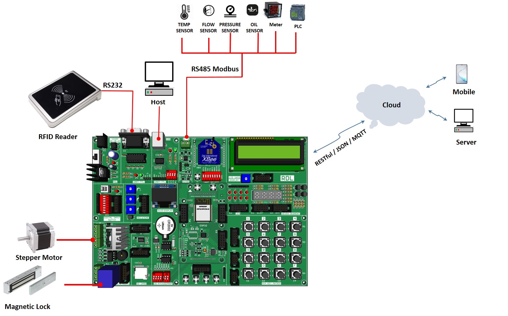
Wiring Diagram:


Applications 

  • Generic Low-power IoT Sensor Hub 

  • Generic Low-power IoT Data Loggers

  • Cameras for Video Streaming

  • Over-the-top (OTT) Devices

  •  Speech Recognition

  •  Image Recognition

  •  Mesh Network

  •  Home Automation

  •  Smart Building 

  •  Industrial Automation 

  •  Smart Agriculture

  •  Audio Applications 

  •  Health Care Applications

  •  Wi-Fi-enabled Toys 

  •  Wearable Electronics

  •  Retail & Catering Applications

 Package Includes   

  • Development Board with Wooden Enclosure

  • USB Cable

  • 12V 2A  Adapter

  • FRC Cable

Documents: 


CLICK HERE to Order Online


I2C 16 Input -Output Port Expander MCP23017


I2C 16 Input -Output Port Expander MCP23017


The IO Expander Board is based on the Microchip MCP23017 Expander Chip. This high-performance IC, allows connection to a range of High-Speed I²C buses, including the standard 100kHz bus, as well as the newer 400kHz and 1.7MHz bus standards. 

ORDER CODE: RDL637

Features:

  • Includes Microchip MCP23017 16-Bit I/O Expander Chip
  • Board can be controlled with High-Speed I²C Connection.
  • Standard Male Headers for Board Interfacing.
  • Suitable for 5V Systems.
  • Three hardware address pins to allow up to eight devices on the bus

MCP23017 Features:


  • 16-bit remote bidirectional I/O port - I/O pins default to input
  • High-speed I2C™ interface (MCP23017) - 100 kHz - 400 kHz - 1.7 MHz
  • Three hardware address pins to allow up to eight devices on the bus
  • Configurable interrupt output pins - Configurable as active-high, active-low or open-drain
  • INTA and INTB can be configured to operate independently or together
  • Configurable interrupt source - Interrupt-on-change from configured register defaults or pin changes
  • Polarity Inversion register to configure the polarity of the input port data
  • External Reset input
  • Low standby current: 1 µA (max.)
  • Operating voltage: - 1.8V to 5.5V @ -40°C to +85°C - 2.7V to 5.5V @ -40°C to +85°C - 4.5V to 5.5V @ -40°C to +125°C


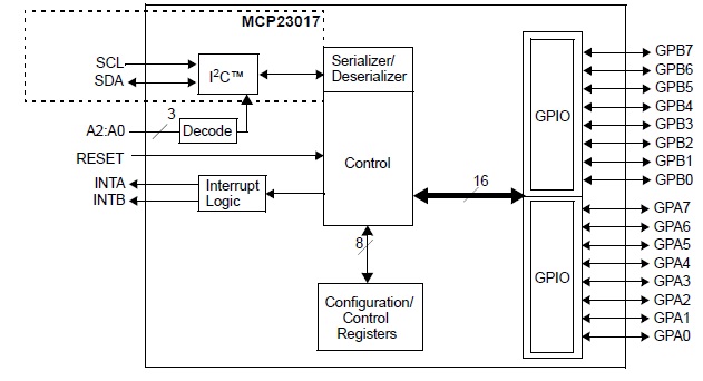
Functional Block Diagram:


Package Contains:


  • IO Expander Board MCP23017 IC+ Male Burgestick

Documents:

  • Datasheet            (I2C 16 Input -Output Port Expander MCP23017)
  • Code                    (Arduino)

CLICK HERE to Order Online

USB 4 Channel Relay Board-FT245RL


USB 4 Channel Relay Board-FT245RL


This relay board with 4 SPDT relays and digital IO controlled via USB protocol, Suitable for home automation applications, hobby projects, and industrial automation. The free software application allows controlling relays manually or automatic operation by creating timers for each channel and enabling repeat cycle. Relay module support Windows & Linux platform, .Net / JAVA / Python SDK available for developing custom application.

Order Code: RDL/4RB/14/001/V4.0


Features:


  • Completely opto isolated relay module

  • LED indication for relay & power supply

  • 4x SPDT Relay (7A 250V, 12A 120V, 10A 125VAC, 10A 28VDC)

  • 4x Digital IO 5v

  • USB Control Chipset FT245RL

  • Greater Power handling PCB 70 Micron with good quality screw Connector 

  • Relay Module Power supply selection available in 5V / 12V / 24 V.

  • Configurable FIFO interface I/O pins.

  • Data transfer rates up to 1Mbyte / second*

  • Fully integrated USB termination resistors.

  • Device supplied pre-programmed with unique USB serial number.

  • USB 2.0 Full Speed compatible.

  • Fully integrated 1024 bit EEPROM storing, device descriptors and FIFO I/O configuration

  • Device supplied pre-programmed with unique USB serial number.

  • Integrated power-on-reset circuit.

  • -40°C to 85°C extended operating temperature range.

  • .Net / JAVA / Python SDK available for developing custom application

applicable for only Digital IO


Specifications:

Max power consumption

300mA

Supply Voltage

5V/12V/24V *

Digital IO Data transfer Rate

1MBPS

Digital IO 5V

4x

Relay

4x , 7A

Relay Max Current

0.21A

Operating temperature

-40°C to 85°C

Opto Isolation

3700VRMS

LED Indication

Power supply & Relay ON

Dimension(L * W)

80MM * 60MM


Applications:

  • Home automation

  • Process Automation

  • Vending Machine

  • Gaming control system

  • Robotics

  • Alarms

  • Timers

  • Remote monitoring and controlling.

  • ATM Security system

  • Aquariums applications


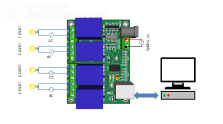
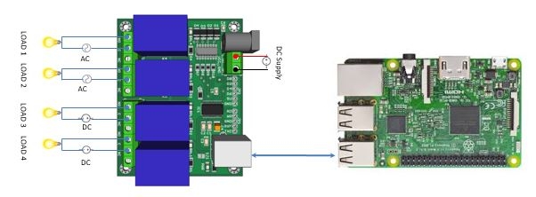
Block Diagram:

A) USB 4 Channel Relay Board to PC

B) USB 4 Channel Relay Board with Raspberry Pi


Package Contains:

  • USB 4 Channel Relay Board-FT245RL.


Documents:


  • Datasheet           (USB 4 Channel Relay Board-FT245RL)

  • Circuit Diagram  (USB 4 Channel Relay Board-FT245RL)

  • Code                    (VB.Net)

  • Driver                  (FTDI)

  • Python Script     (Windows)

  • Software             (F245RL Utility Software)

  • Software             (Programable Software)

  • Software             (F245RL MATLAB SDK Software)

  • Support               (FTDI Support)

  • Manual                 (FTDI Manual)

  • Application Note (FTDI Application Note)


CLICK HERE to Order Online