ESP32 IoT Development Trainer Kit
Start Your IoT Journey Today..!
ESP32 essential development features a plug and play design that makes it easy for connections and helps Students, hobbyists, enthusiasts, and professionals to focus more on Program / application development. ESP32 IoT Trainer Kit equipped with on board IO’s, communication interfaces & peripherals. It is really easy to design, experiment with, and test circuits without soldering. It’s used in many educational institutions and R&D LAB across the world.
ORDER CODE: RDL814

Features:
Board Features
On Board Programming.
Plug & Play Interface Connectivity.
Professional EMI/RFI Complaint PCB Layout Design
Modular Block design makes Easy access & quick Prototyping
FRC connectivity features minimize the connection Error.
High Quality Grade PCB with wooden Enclosure.
8 interfacing LED’s.
1 * 4 Menu keypad.
4* 4 Matrix Keypad.
RS232, RS485, USB communication port.
7 Segment Multiplexed Display.
16*2 LCD & OLED Display
ADC & DAC Card.
8 bit 4 port IO.
On Board WiFi/Bluetooth Connectivity
3.3 to 5V Level Converter.
Power Supply 3.3V and 5V
SD CARD Interface.
RTC & EEPROM Interface.
DC Motor/ Stepper Motor Driver.
Relay, Buzzer.
1xTemperature Sensor.
3x Analog Test POT.
MCU
ESP32-D0WD-V3 embedded, Xtensa® dual-core 32-bit LX6 microprocessor, up to 240 MHz
448 KB ROM for booting and core functions
520 KB SRAM for data and instructions
16 KB SRAM in RTC
4 MB SPI flash
Wi-Fi
802.11b/g/n
Bit rate: 802.11n up to 150 Mbps
A-MPDU and A-MSDU aggregation
0.4 µs guard interval support
Center frequency range of operating channel: 2412 ~ 2484 MH
Bluetooth® / BLE
Bluetooth V4.2 BR/EDR and Bluetooth LE specification
Class-1, class-2 and class-3 transmitter
AFH
CVSD and SBC
Hardware
Interfaces: SD card, UART, SPI, SDIO, I2C, LED PWM, Motor PWM, I2S, IR, pulse counter, GPIO, capacitive touch sensor, ADC, DAC, Two-Wire Automotive Interface
Communication Interface : RS232 , RS485 ( Modbus RTU ) , USB , SPI , I2C .
On Board Peripheral : OLED Display , 16x2 LCD Display,Seven Segment Display ,8x LED , 4x4 Hex Keypad , 1x4 Menu Keypad , Xbee Adapter, 3.3 to 5v Level Converter, SD CARD Interface, RTC & EEPROM, DC Motor / Stepper Motor Driver, Relay, Buzzer,1xTemperature Sensor,3x Analog Test POT ,8x Selection DIP Switch.
Scope of Learning Experiments:
LED blinking.
8 bit LED Left shift, Right shift and counting operation.
Keypad Interrupt Interface
16*2 LCD interface.
Matrix Keypad Interface.
ADC& DAC interface.
Traffic Light Signal Interface.
8 bit DIP switch interface.
7 Segment interface.
L298 Driver for DC Motor and Stepper motor interface.
Elevator Interface.
Buzzer, Relay interface.
RS485, RS232 serial communication.
UART Operation
RTC DS1307I2C protocol interface.
AT24C04 EEPROM I2C protocol interface.
RF/WiFiCommunication.
Temperature Sensor Interface.
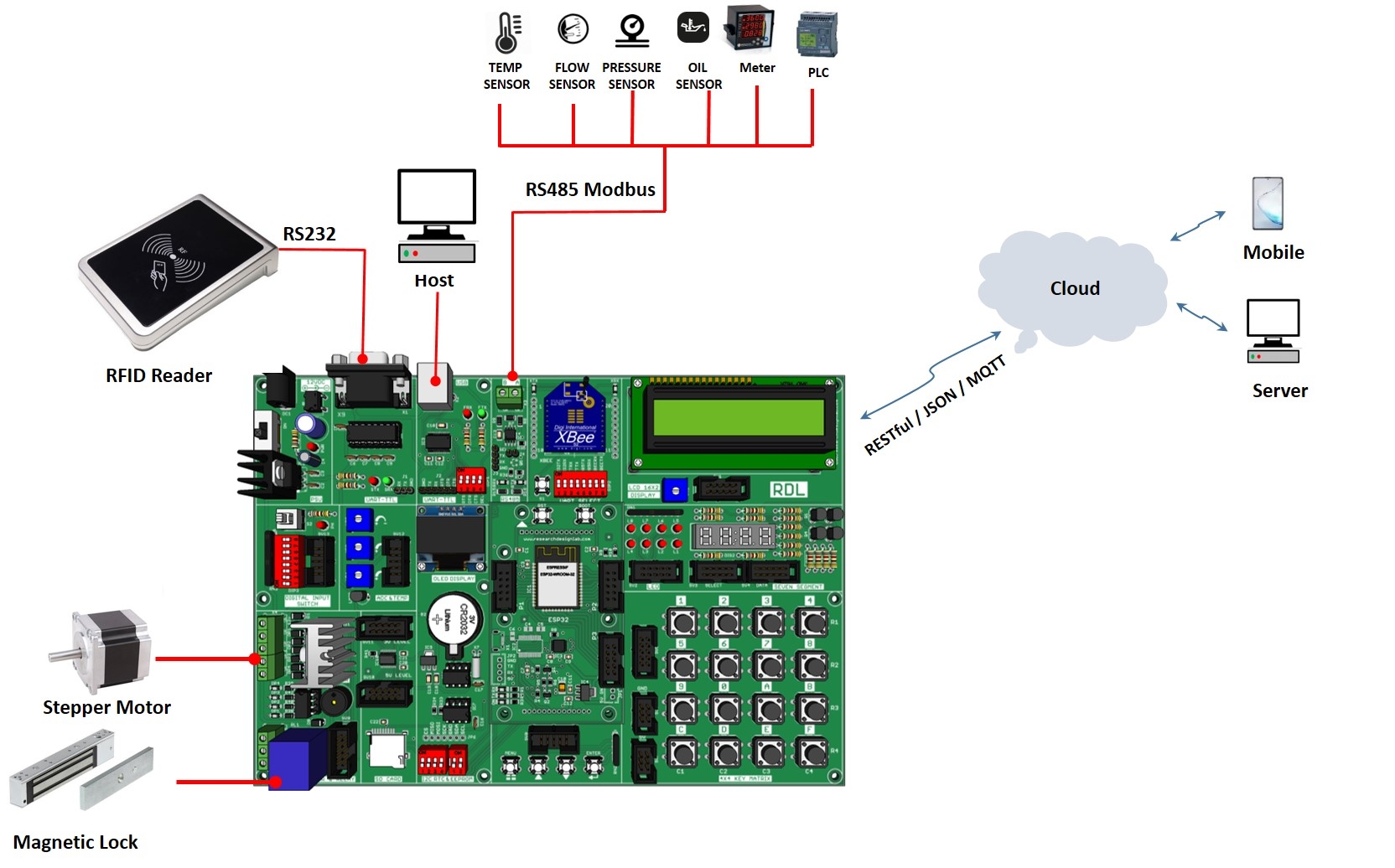
Wiring Diagram:

Applications
Generic Low-power IoT Sensor Hub
Generic Low-power IoT Data Loggers
Cameras for Video Streaming
Over-the-top (OTT) Devices
Speech Recognition
Image Recognition
Mesh Network
Home Automation
Smart Building
Industrial Automation
Smart Agriculture
Audio Applications
Health Care Applications
Wi-Fi-enabled Toys
Wearable Electronics
Retail & Catering Applications
Package Includes
Development Board with Wooden Enclosure
USB Cable
12V 2A Adapter
FRC Cable


No comments:
Post a Comment