Pages

Monday, 10 January 2022

Vibration Sensor


Vibration sensor is designed to track asset’s health and provide insights of asset conditions to the maintenance teams that may lead to equipment failure & avoid the need for major repairs. Vibration sensors are commonly used in predictive maintenance and condition monitoring.


Features

  • 3-axial MEMS accelerometer

  • Configurable communication mode RS485 Modbus RTU / WiFi / Bluetooth

  • Support monitoring 10 different set frequency components of the system.

  • Built in FFT Algorithm for vibration analysis

  • High resolution & measurement at up to ±16 g

  • Configurable Measuring Range  ±2, ±4, ±8, ±16

  • Configurable Bandwidth up to 3.2KHz


Applications


  • Machine vibration monitoring, e.g.  Motors, Compressors, AHU, Gearbox, Pump etc.

  • Vibration measurement and alarm triggering.

  • Predictive maintenance and Condition monitoring.


Documents

Tuesday, 28 December 2021

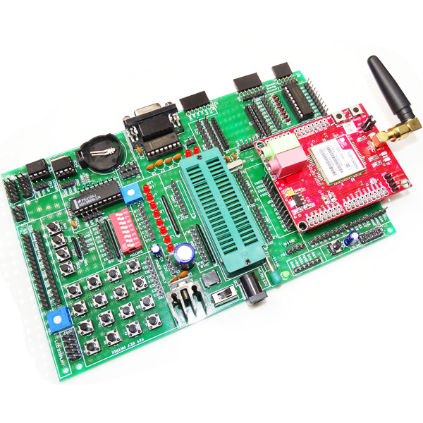
PIC Development Board-Trainer Kit


Start Your Embedded System Design Journey Today..!

PIC essential development features a plug and play design that makes it easy for connections and helps Students, hobbyists, enthusiasts, and professionals to focus more on Program / application development. PIC Development Board Trainer kit equipped with on board IO’s, communication interfaces & peripherals. It is really easy to design, experiment with, and test circuits without soldering. It's used in many educational  institutions and R&D LAB across the world.

ORDER CODE: RDL740

Features:

  • Plug & Play Interface Connectivity.

  • Professional EMI/RFI Complaint PCB Layout Design

  • Modular Block design makes Easy access & quick Prototyping 

  • FRC connectivity features minimize the connection Error.

  • High Quality Grade PCB with wooden Enclosure. 

  • 8 interfacing LED’s.

  • 1 * 4 Menu keypad.

  • 4* 4 Matrix Keypad.

  • RS232, RS485, USB communication port.

  • 7 Segment Multiplexed Display.

  • 16*2 LCD & OLED Display

  • ADC & DAC Card.

  • 8 bit 4 port IO.

  • On Board WiFi / Bluetooth Connectivity

  • 3.3 to 5V Level Converter.

  • Power Supply 3.3V and 5V

  • SD CARD Interface.

  • RTC & EEPROM Interface.

  • DC Motor/ Stepper Motor Driver.

  • Relay, Buzzer.

  • 1xTemperature Sensor.

  • 3x Analog Test POT.

MCU


  • Only 35 single-word instructions to learn

  • All single-cycle instructions except for program branches, which are two-cycle

  • Operating speed: DC – 20 MHz clock input DC – 200 ns instruction cycle

  • Up to 8K x 14 words of Flash Program Memory, Up to 368 x 8 bytes of Data Memory (RAM), Up to 256 x 8 bytes of EEPROM Data Memory

  • Pinout compatible to other 28-pin or 40/44- pin PIC16CXXX and PIC16FXXX microcontrollers


Analog Features


  • 10-bit, up to 8-channel Analog-to- Digital Converter(A/D)


Peripheral Features


  • Timer0: 8-bit timer/counter with 8-bit prescaler

  • Timer1: 16-bit timer/counter with prescaler,

  • Timer2: 8-bit timer/counter with 8-bit period register,prescaler and postscaler

  • Two Capture, Compare, PWMmodules

  • Synchronous Serial Port (SSP) with SPI™ (Mastermode)and I2C™ (Master/Slave)

  • Universal  Synchronous Asynchronous Receiver Transmitter(USART/SCI) with 9-bit address detection

  • Parallel Slave Port (PSP) – 8 bits wide with external RD,WR and CS controls (40/44-pin only)


Scope of Learning Experiments:


  • LED blinking.

  • 8 bit LED Left shift, Right shift and counting operation.

  • Keypad  Interrupt Interface

  • 16*2 LCD interface.

  • Matrix Keypad Interface.

  • ADC& DAC interface.

  • Traffic Light Signal Interface.

  • 8 bit DIP switch interface.

  • 7 Segment interface.

  • L298 Driver for DC Motor and Stepper motor interface.

  • Elevator Interface.

  • Buzzer, Relay interface.

  • RS485, RS232 serial communication

  •  PWM Interface

  • UART Operation

  •  RTC DS1307I2C protocol interface.

  • AT24C04 EEPROM I2C protocol interface.

  • RF/WiFiCommunication.

  •  SPI protocol interface

  • Temperature Sensor Interface.


Supported IC:

PIC16F74      PIC16F77     PIC16F747     PIC16F777    PIC16F871    PIC16F874    PIC16F877   PIC16F877A  PIC16F887   PIC18F452   PIC18F458  PIC18F4220  PIC18F4320  PIC18F4431  PIC18F4331   PIC18F4520   PIC18F4420   PIC18F4550  PIC18F4455    PIC18F4580   PIC18F4480  PIC18F4585   PIC18F4680    PIC18F4620    PIC18F45J10  PIC18F44J10   PIC18F44J   PIC18F43K20  PIC18F44K20  PIC18F46K20 


Package Contains :

  • Development Board with Wooden Enclosure
  • USB Cable.
  • 12V 2A Adapter.
  • FRC Cable


Documents:


Codes:

  • Code (LED Sequence with Select Keys)
  • Code  (7 Segment Display)
  • Code (RTC and 7 Segment)


MP LAB(HI-TECH_C) Sample Codes:


8051 Development Board- Trainer Kit


Start Your Embedded System Design Journey Today..!
8051 essential development features a plug and plays design that makes it easy for connections and helps Students, hobbyists, enthusiasts, and professionals to focus more on Program/application development. 8051 Development Trainer kit equipped with onboard IO’s, communication interfaces & peripherals. It is really easy to design, experiment with, and test circuits without soldering. It’s used in many Educational Institutions and R&D LAB across the world.

ORDER CODE: RDL847


Features:

  • Plug & Play Interface Connectivity.

  • Professional EMI/RFI Complaint PCB Layout Design

  • Modular Block design makes Easy access & quick Prototyping 

  • FRC connectivity features minimize the connection Error.

  • High Quality Grade PCB with wooden Enclosure. 

  • The DIP40 locking device for reuse ATMEL microcontroller.

  • Supports 8051, AT89SXX and AT89CXX series chips 40 pin DIP package.

  • On Board Programming.

  • 8 interfacing LED’s.

  • 1 * 4 Menu keypad.

  • 4* 4 Matrix Keypad.

  • RS232, RS485, USB communication port.

  • 7 Segment Multiplexed Display.

  • 16*2 LCD & OLED Display

  • ADC & DAC Card.

  • 8 bit 4 port IO.

  • On Board WiFi / Bluetooth Connectivity

  • 3.3 to 5V Level Converter.

  • Power Supply 3.3V and 5V

  • SD CARD Interface.

  • RTC & EEPROM Interface.

  • DC Motor/ Stepper Motor Driver.

  • Relay, Buzzer.

  • 1xTemperature Sensor.

  • 3x Analog Test POT.


Scope of Learning Experiments:

  • LED blinking.

  • 8 bit LED Left shift, Right shift and counting operation.

  • Keypad  Interrupt Interface

  • 16*2 LCD interface.

  • Matrix Keypad Interface.

  • ADC& DAC interface.

  • Traffic Light Signal Interface.

  • 8 bit DIP switch interface.

  • 7 Segment interface.

  • L298 Driver for DC Motor and Stepper motor interface.

  • Elevator Interface.

  • Buzzer, Relay interface.

  • RS232 serial, RS485 and USB communication.

  • UART Operation

  • RTC DS1307I2C protocol interface.

  • AT24C04 EEPROM I2C protocol interface.

  • RF/WiFi Communication.

  • Temperature Sensor Interface.

NOTE : Look into the datasheet for more details


Package Includes:

  • Development Board with Wooden Enclosure

  • USB Cable.

  • 12V 2A Adapter.


Documents:


Monday, 13 December 2021

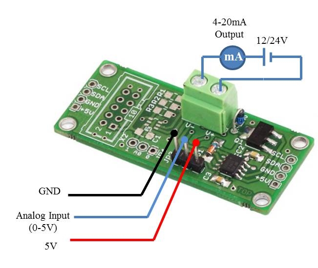
4-20mA Current Loop Transmitter


    4-20mA Current Loop Transmitter XTR116U with Analog Input


The XTR116 are precision current output converters are designed to transmit analog 4-to- 20mA signals over an industry standard current loop. They provide accurate current scaling and output current limit functions.


Features:

  • Low Quiescent Current: 200µA
  • VREF for sensor excitation:XTR116: 4.096V
  • Low span error: 0.05%
  • Low nonlinearity error: 0.003%
  • Wide loop supply range: 7.5V to 36V
  • SO-8 Package
  • I2C Interface.

Specifications

Supply Voltage

7.5 V ~ 36 V

Loop Current Range

0-20mA / 4 -20mA

Temperature Range

-40°C to +85°C

Low Quiescent Current

200µA

Wide Loop Supply Range

7.5V to 36V

Current Gain

100

Noise

0.1Hz to 10 Hz

Small Signal Bandwidth

380 KHz

Slew Rate

3.2 mA/µs

Dimensions(L*W)

54 * 23 MM


Applications:

  • 2-Wire, 4-20mA Current Loop Transmitter
  • Smart Transmitter
  • Industrial Process Control
  • Test Systems
  • Compatible with Hart Modem
  • Current Amplifier
  • Voltage-To-Current Amplifier.


Analog 4-20mA Transmitter 


Package Contains :   

  • 4-20mA Current Loop Transmitter XTR116U with Analog Input

Documents:

Friday, 10 December 2021

8051 AT89S52 Development Board


8051 AT89S52 Development Board

8051 are popular with both industrial developers and hobbyists alike due to their low cost, wide availability, large user base, extensive collection of application notes, availability of low cost or free development tools, and serial programming (and re-programming with flash memory) capability. They are also commonly used in educational programming .

Order Code : RDL/8DB/14/001/V1.0

Features:

  • High quality Atmel microcontroller development board.
  • The DIP40 locking device, easy to remove the ATMEL microcontroller for reuse.
  • 8 independent LED.
  • 1 * 4 independent keys.
  • 4* 4 keypad matrix.
  • RTC DS1307 with battery connector
  • AT24C02 I2C external memory.
  • I2C EEPROM Interfaces
  • The MAX232 chip RS232 communication.
  • 16X2 LCD interface (character display).
  • All IO ports pin have extraction and clearly marked.
  • On Board Power supply 3.3V,5V 12V,GND.
  • 8 pin DIP switches.
  • RS232 Connector.
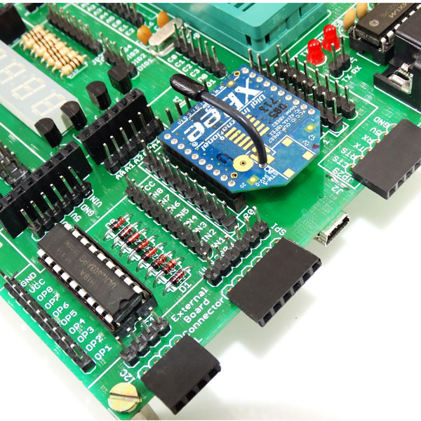
  • The board also has inbuilt Xbee footprint.
  • Stackable Arduino shields.
  • Raspberry Pi expansion connectors.
  • ADC0804 8-Bit Microcontroller Compatible A/D Converter.
  • I2C bus.
  • SPI Bus.
  • FT232 Breakout board connector.
  • External jumper nodes.
  • Board is equipped with LCD 2x16 connector 
  • Quartz crystal 11.0592 MHz.
  • ULN 2803 To drive Stepper Motor& Relays.
  • Reset button.
  • Power plug-in DC Socket.
  • Power supply indicator LED.
  • Test led for Tx, Rx.
  • 7Seg Multiplexed Display.
  • Pin outs for 3.3V,12V,5V,GND.
  • All IO’s are connected by brug stripps for easy connection.
  • High quality PCB FR4 Grade with FPT Certified.
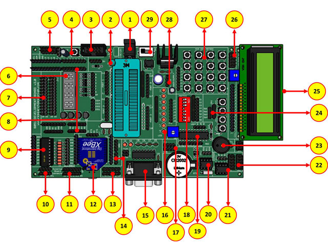
 

1.  Power supply, 5V-12V

2.  40 pin ZIF socket for IC mount.

3.  ISP connector*

4.  Reset

5.  Node connector

6.  4x1  7 segment display

7.  26 pin raspberry connector

8.  Arduino Shield footprint

9.  ULN 2803 driver

10. I2C bus

11. SPI bus

12. XBEE footprint/ XBEE Adaptor module

13. FT232 breakout board connector

14. DC 3.3V connectors

15. DB-9 female connector

16. 8x1 LED’s

17.DC 5V connectors

18.8 way DIP switch

19.Analog to Digital output

20.RTC Module

21. EEPROM

22. 2x5x2 jumper node.

23.Buzzer

24.4x1 keypad

25.16x2 LCD connectors

26.Node connector

27.4x4 Matrix Keypad

28.DC 12V connectors

29.Power ON switch

 *It require additional programmer to burn the chip through ICD ICSP socket.

 Stackable Arduino shields
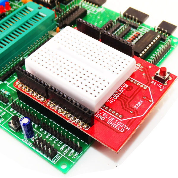

Xbee footprint
 

Package Contains :

  • 8051/AT89S52 Development Board + LCD.

Documents:

Schematic:

Codes:


  • Code (Stepper Motor)