Pages

Friday, 9 April 2021

Digital Dimmer Module

INTRODUCTION

The board uses BTA12-600B,Triac suitable for general purpose mains power AC switching. They can be used as ON/OFF function in applications such as static relays, heating regulation or induction motor starting circuit. They are also recommended for phase control operations in light dimmers and appliance motors speed controllers.

The dimmer board enabled with snubber circuit, especially recommended for use on inductive loads (Motor/Fan), because of their high commutation performance. The dimmer board controls up to 0-600V AC 50/60Hz.4 bit 16 levels of input can be given from any controllers/PLC to control dimming 0-100% or ON/OFF


 Features:

  • Dimming method : Phase dimming
  • On/Off and dimming control.
  • Circuit enabled with snubber.
  • Auto Zero cross detection
  • Accurate firing angle control and smooth dimming.
  • Operating Voltage 12V/24V DC.
  • Isolated power section from the input.
  • 0-100% dimming.
  • Load Capacity 6 Amp AC (Up to 1500 Watt).
  • Works from any microcontroller input.
  • Control up to 250V.

Applications :

  • LED light dimming using phase control
  • Motor/Fan speed control
  • High speed ON/OFF control application
  • Heater/Temperature control application
  • PID Temperature control System
  • PID AC single phase speed control system.


Specifications:

Digital Input Voltage(D0-D1)Max input voltage 5V
Operating Voltage5V
Control level (0-100%)16 level digital input
Triac Max Load current6A
Max Voltage250V
Frequency50/60 Hz
Dimension (L * W)50MM * 30MM
Weight20g


Dimmer module-Control:

Table shows 16 level of dimming control of load 0-100%

INPUT

OUTPUT

D3

D2

D1

D0

    Dimming %

         1

         1 

         1

       1 

       0%

         1

         1

         1

       0

       5%   

         1

         1

         0

       1

      10%

         1

         1

         0

       0

      15%

         1

         0

         1

       1

      20%

         1

         0

         1

       0

      25%

         1

         0   

          0

       1

      30%

         1

         0

          0

       0

      40%

         0

         1

          1

       1

      50%

         0

         1

          1

       0

      60%

         0

         1

          0

       1

      65%

         0

         1

          0 

       0

      70%

         0

         0

          1

       1

      75%

         0

         0

          1

       0

      80%

         0  

        0  

          0

       1

      85%

         0

        0

          0

       0

     100%


CLICK HERE for User Manual

CLICK HERE to Order Online

Wednesday, 7 April 2021

LiFi Visible Light Communication Compatible for Raspberry Pi


LiFi Visible Light Communication Compatible for Raspberry Pi


RPI Li-Fi Shield is a plug-and-play evaluation board for developing a wide array of visible light communication applications in consumer, wearable, industrial, medical and Internet of Things (IoT). RPI Li-Fi Shield transfers data from one source to another through visible light without the flickering effect. Technically, 1‟s (LED on) and 0‟s (LED off) are modulated and then transmitted at very high speed.


Features:

  • Supports baud rates up to 38400
  • Support serial (UART) communication
  • Supported distance from the ceiling 6 to 15 feet max
  • Plug-and-Play with simple configuration
  • Ceiling / wall mounting LED light can be used for the communication

Specifications

  Supply Voltage

  5V,2A

  Supported MAX Load (LED)

  15W

  Baud Rate

  34500

  Max communication Distance *

  15 feet

  Communication

  One way

  Communication Type

  Serial UART

  Communication Light Spectrum

  Visible light 400 to 700nm

  Dimension(L * W)

  58MM * 49MM


* Supported distance from the ceiling 6 to 15 feet max


Applications:

  • Indoor wireless open optical communication.
  • Indoor navigation.
  • Under water visible light communication.
  • Smart indoor blind assistive application.
  • Vehicle to vehicle communication.
  • Monitor as transmitter for Data Communication.
  • Preventing Phishing Attacks using One Time Password and User Machine Identification.
  • Super market navigation system and discount information based on location.
  • Smart LIFI based Car Parking system.
  • Smart Location Aware of Services.
  • Visible light positioning for asset tracking.
  • POSITIONING TECHNIQUES FOR ACCURATE LOCALIZATION mobile robot navigation.
  • Integrated, underwater optical /acoustic communications system.
  • Visible Light Communication Based Traffic Information Broadcasting Systems.

Compatibility:

  • Raspberry Pi
  • Raspberry Pi 2
  • Raspberry Pi 3
  • Raspberry Pi 4
  • Raspberry Pi Model B+
  • Raspberry Pi Zero

Package Contains :

  • LiFi (Visible Light Communication) Compatible for Raspberry Pi + LED Light
Note1 : The Raspberry Pi in the picture above is just for reference , it does not include in the package.

CLICK HERE for User Manual 

CLICK HERE to Order Online


LiFi Nano V2


LiFi Nano v2 is an easy-to-use, plug-and-play evaluation platform for a wide array of visible light communication applications in consumer, wearables, industrial, medical and Internet of Things (IoT) markets.LiFi Nano consists of two modules, LiFi transmit module connected to the lighting LED and LiFi receive module connected to the host communicating system.


Feature

  • Support baud rate 38400.
  • 6-15 feet distance, distance can be increased by changing the LED wattage.

  • High intensity LED Light.

  • Domestic Ceiling / wall mounting focus LED light can be used for communication.

  • Plug-and-Play with simple configuration.


Transmitter Connection Diagram:


Receiver Connection Diagram:


Applications:

  • Indoor wireless open optical communication.

  • Indoor navigation.

  • Under water visible light communication.

  • Smart indoor blind assistive application.

  • Vehicle to vehicle communication.

  • Monitor as transmitter for Data Communication.

  • Preventing Phishing Attacks using One Time Password and User Machine Identification.

  • Super market navigation system and discount information based on location.

  • Smart LIFI based Car Parking system.

  • Smart Location Aware of Services.

  • Visible light positioning for asset tracking.

  • POSITIONING TECHNIQUES FOR ACCURATE LOCALIZATION mobile robot navigation.

  • Integrated, underwater optical /acoustic communications system.

  • Visible Light Communication Based Traffic Information Broadcasting Systems.

  • Li-Fi wireless optical communication

Package Contains :

RDL749:

  • Li Fi Transmitter - 1 No
  • Li Fi Reciever- 1No
  • LED Light - 1 No
  • Constant Current LED Driver - 1 No
  • FT232RL Breakout Board - 1 No
  • USB Cable - 1 No
  • Jumper Wires

RDL749A:

  • Li Fi Transmitter-4 No's
  • Li Fi Reciever - 1 No
  • LED Light - 4 No's
  • Constant Current LED Driver - 4 No's
  • FT232RL Breakout Board-4 No's
  • USB Cable-4 No's
  • Jumper Wires
CLICK HERE for User Manual


Monday, 5 April 2021

Industrial Data Logger 4G LTE


INTRODUCTION

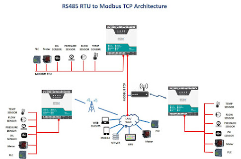
The product is designed to seamlessly integrate with the IoT and Analytical processing systems. Supporting multiple I/O options, interfaces data logger is a perfect fit to build custom automation solutions. Industrial Data Logger 4.0 can used to build the custom industrial solution for monitoring and controlling PLC and SCADA, HMI, VFD Motors, servo, Valves, energy meter, actuators, relays, encoder, rfid and finger print readers, industrial sensors and many more with below mentioned operational benefits.


Features

  • 12 x isolated Analog Input Channel 0-10V , 0-24v , 4-20mA.                                                      
  • 4x isolated Digital input 24V
  • 3x Isolated digital output / PWM 24v
  • 1x Relay ( NO & C)
  • 1x Isolated RS485 for MODBUS RTU communication
  • 1x Isolated Ethernet 10/100Mbps MODBUS TCP Communication
  • 1x USB-device interface for configuring, monitoring and download
  • 1x WIFI / 2G / 4G / LTE wireless communication
  • Configure and Read Multiple Slave IDs, Selectable Input Register Holding Register & Coil.
  • Configurable  Data type and Conversion method (INT ,Long INT , FLOAT , Double Float & Raw Hex)
  • Configurable Scaling factor enabling option for Analog channel .
  • Configurable WIFI / GPRS / 4G / LTE Interface 
  • Configurable data transferring protocol JSON / MQTT and FTP
  • Support secure communication SSL
  • Custom Configurable polling interval
  • Custom Configurable 32 bit counter input
  • 8 GB inbuilt storage
  • Data Logs and stores its CSV file during network failure
  • Logger Sends offline data once Network and Server Connected
  • Configurable Live / Schedule upload offline data
  • Remote control / Activating Relay / Digital output
  • Configurable Alarm
  • OTA (Over The Air) Firmware upgrade for WIFI devices.
  • LED indicators to indicate Power, Network availability, status & Fault.
  • Auto Maintain socket / server  connection
  • Easy configurable connectivity for  cloud platform AWS / Azure / Google / Oracle / Things board

Application

  • Production and process monitoring
  • Utilities monitoring
  • Condition monitoring
  • Environment monitoring
  • Industrial Smart grid
  • Solar grid
  • Cold storage monitoring
  • District metering
  • Water treatment
  • Generator monitoring
  • Green House


ORDER INFORMATION TABLE


 CLICK HERE  for schematic and samples

CLICK HERE for User Manual 

CLICK HERE to Order Online

Saturday, 3 April 2021

ESP32 IoT Development Trainer Kit


INTRODUCTION

ESP32 IoT Development Trainer Kit is a single board IoT edge computing device equipped with   on board IO’s, communication interfaces & peripherals. It  is really easy to design, experiment with,   and test circuits without soldering. Students, hobbyists ,enthusiasts, and professionals can explore   wide variety of IoT concepts simply by connecting FRC cable & integrating with the cloud platform


FEATURES

MCU 

  • ESP32-D0WD-V3 embedded, Xtensa® dual-core 32-bit LX6 microprocessor, up to 240 MHz 

  • 448 KB ROM for booting and core functions

  • 520 KB SRAM for data and instructions 

  • 16 KB SRAM in RTC

  •  4 MB SPI flash


Wi­Fi 

  •  802.11b/g/n 
  •  Bit rate: 802.11n up to 150 Mbps
  •  A-MPDU and A-MSDU aggregation 
  •  0.4 µs guard interval support
  •  Center frequency range of operating channel: 2412 ~ 2484 MH

Bluetooth® / BLE

  •   Bluetooth V4.2 BR/EDR and Bluetooth LE specification

  •  Class-1, class-2 and class-3 transmitter

  •  AFH

  •  CVSD and SBC


Wiring Diagram


Package Includes  
 
  • Development Board with Wooden Enclosure
  • USB Cable
  • 12V 2A  Adapter
  • FRC Cable
FOR SCHEMATIC AND SAMPLES CLICK HERE
TO ORDER ONLINE CLICK HERE 


Thursday, 14 November 2019

MQTT_Linux_Bringup_ver1.1


Steps to configure and bring up Mosquitto MQTT Broker on AWS EC2


Mainly 2 steps
1.Bring up EC2 Linux System
2.Install mosquitto on the above system
Bring up EC2 Linux System


Steps to configure and bring up Mosquitto MQTT Broker on AWS EC2


Steps to configure and bring up Mosquitto MQTT Broker on AWS EC2


Steps to configure and bring up Mosquitto MQTT Broker on AWS EC2


Steps to configure and bring up Mosquitto MQTT Broker on AWS EC2


Steps to configure and bring up Mosquitto MQTT Broker on AWS EC2


 Steps to configure and bring up Mosquitto MQTT Broker on AWS EC2


 Steps to configure and bring up Mosquitto MQTT Broker on AWS EC2

RDL Copyright 8 st Nov 2019
Installation of mosquitto on linux system
Follow the below steps to install mosquitto
1. sudo apt-add-repository ppa:mosquitto-dev/mosquitto-ppa
2. sudo apt-get update
3. sudo apt-get install mosquitto
4. sudo apt-get install mosquitto-clients
Follow the below steps to Enable user authentication
 Create a txt file in the following format
 Username:Password
 Issue the following commands to add certificate to this file
 mosquitto_passwd -U passwordfile (text file name)
 Copy this file to /etc/mosquitto
Open mosquiito.conf  and add these 2 lines to enable user authentication
allow_anonymous false
password_file  etc\mosquitto\passwords.txt 
Restart the broker to absorb the changes
ubuntu@ip-172-31-36-216:~$ mosquitto -v
1572603369: mosquitto version 1.6.7 starting
1572603369: Using default config.
1572603369: Opening ipv4 listen socket on port 1883.
1572603369: Error: Address already in use
To resolve this
ps –ef | grep mosquitto
kill -9 pid
mosquitto_sub -t '$SYS/#' –v
or
root@ip-172-31-36-216:/home/ubuntu# mosquitto
1572603616: mosquitto version 1.6.7 starting
1572603616: Using default config.
1572603616: Opening ipv4 listen socket on port 1883.

1572603616: Opening ipv6 listen socket on port 1883.


 Steps to configure and bring up Mosquitto MQTT Broker on AWS EC2

To enable Message flow on to AWS ES2 system, follow the below steps
Create Security Group to allow TCP/1883 traffic in the inbound direction


                                     Add the Security Group to the Next Interface associated to the EC2 resource


Steps to configure and bring up Mosquitto MQTT Broker on AWS EC2

On MQTTFx client, include Public domain IP4 address as Broker Address


                                    Provide user credentials configured in the password.txt on the MQTT broker


Steps to configure and bring up Mosquitto MQTT Broker on AWS EC2

Mosquitto SSL Configuration -MQTT TLS Security

Server Side: Openssl tool is used to generate the required keys and certificats for both
the server and client
Issue the following commands in sequence and make changes to the
mosquitto.conf on the server for the changes to take effect

1. openssl genrsa -des3 -out ca.key 2048 2.  openssl req -new -x509 -days 1826 -key ca.key -out ca.crt 3. openssl genrsa -out server.key 2048 4. openssl req -new -out server.csr -key server.key 5. openssl x509 -req -in server.csr -CA ca.crt -CAkey ca.key -CAcreateserial -out server.crt -days 360
The directory file listing would look similar to the below


Copy the ca.crt, server.crt and server.key file to /etc/mosquitto/cert folder

Make the following changes to the mosquitto.conf file

Add the following lines

Port 8883

Cafile /etc/mosquitto/certs/ca.crt

Keyfile /etc/mosquitto/certs/server.key

Certfile /etc/mosquitto/certs/server.crt

Most important step is to copy the ca.crt on to the client system.

Incase its get challenging to transfer this file, as it would from AWS EC2 environment. Please use
notepad+ (not plain notepad) to copy paste the certificate contents

Client Side: Configure the MQTT Client with the broker address, enable SSL and point to the ca.crt
file and connect for application.


For reference: https://researchdesignlab.com/projects/MQTT_Linux_Bringup_ver1.0.pdf