Pages

Thursday, 12 September 2019

ESP32-RTC (Real Time Clock)

ESP32-RTC (Real Time Clock)

Aim:

To display Date and Time on the serial monitor using ESP 32 microcontroller development board.

Description:

Interfacing Real Time Clock module with ESP 32 to display date and time on the serial monitor.

Hardware required:

ESP32-Microcontroller Development board

Pin connection:


Pin Mapping:

RTC
ESP32
SDA
I021
SCL
I022

Procedure:
1.        The above pin connection shows how to display date and time using RTC in ESP32 board.
    2.        Do the connections as shown in the pin diagram and pin mapping.
    3.        Connect the USB cable to the board.
    4.        Open Arduino IDE .Select DOIT ESP32 DEVKIT V1in boards and select COM port.
    5.        Verify the program and Upload it.
    6.        Open the serial monitor to observe the output.


Program:


/* Date and time functions using a DS1307 RTC connected via I2C and Wire lib */ #include<Wire.h>
#include"RTClib.h"    RTC_DS1307RTC;
charrec;

void setup(void)
{
Serial.begin(9600); 
Wire.begin();
RTC.begi n(); 
delay(1000);
//while(!Serial.available());
//{
// rec=Serial.read();
// if(rec=='2')
/* This line sets the RTC with an explicit date & time, for example to set January 16, 2019 at 12.32pm you would call: rtc.adjust(DateTime(2019, 1, 16, 12, 32, 45)) */
RTC.adjust(DateTime("Mar 22 2019","10:32:45"));

//}
}

void loop(void)
{
/*Getting the current Time and storing it into a DateTime object */ DateTimenow=RTC.now();

Serial.print(now.year(),DEC); 
Serial.print('/'); Serial.print(now.month(),DEC); 
Serial.print('/'); Serial.print(now.day(),DEC); Serial.print(' ');
Serial.print(now.hour(),DEC); 
Serial.print(':'); Serial.print(now.minute(),DEC); 
Serial.print(':'); Serial.print(now.second(),DEC); 
Serial.println();
delay(1000);
}


Thursday, 5 September 2019

ESP32-CONTROLLING LED BRIGHTNESS


ESP32-CONTROLLING LED BRIGHTNESS

Aim:

To vary the intensity of LED using potentiometer.

Description:

This experiment shows how to read an analog input value connected to onboard pot and display it on the serial monitor of the Arduino Software (IDE).

Hardware required:


ESP32-Microcontroller development board

Pin connection:


Pin Mapping:

Development Board
ESP32
Potentiometer
I034
LED
I05

Procedure:
1.        The above pin connection shows how to control the brightness of LED using potentiometer in ESP32 board.
2.        Do the connections as shown in the pin diagram and pin mapping.
3.        Connect the USB cable to the board.
4.        Open Arduino IDE .Select DOIT ESP32 DEVKIT V1in boards and select COM port.
5.        Verify the program and Upload it.
6.        Open the serial monitor to observe the values.
7.        Now using a screw driver rotate the potentiometer. The LED will be very bright at the highest point and low as you turn the potentiometer in the opposite direction.

Program:

void setup(void)
{
/* set baud rate */
Serial.begin(9600);

/* Initialize the input pin */ pinMode(34,INPUT);

/* Initialize the output pin */ pinMode(5,OUTPUT);
}

/* the loop function runs over and over again forever */ 
void loop(void)
{
int outputvalue=analogRead(34);
int value=map(outputvalue,0,1023,0,255); 
analogWrite(5,outputvalue);
/* Print a value on the serial monitor */ Serial.println(outputvalue); delay(1000);
}

ESP32-LIQUID CRYSTAL DISPLAY

ESP32-LIQUID CRYSTAL DISPLAY

Aim:


This experiment shows how to display the message on LCD using ESP32-Microcontroller.

Description:

To display the message on the LCD screen.

Hardware required:


ESP32-Microcontroller Development board.


Pin connection:

Pin Mapping:

LCD
ESP32
RS
I04
E
I012
D4
I032
D5
I033
D6
I025
D7
I026
R/W
GND

Procedure:
1.        The above pin connection shows how to interface LCD with ESP32 board.
2.        Do the connections as shown in the pin diagram and pin mapping.
3.        Connect the USB cable to the board.
4.        Open Arduino IDE .Select DOIT ESP32 DEVKIT V1in boards and select COM port.
5.        Verify the program and Upload it.
6.        Now you can see the output displaying the message on LCD of ESP32 microcontroller board.

Program:

/* Include the LCD library */ #include<LiquidCrystal.h>

/* Mapping the pins with library rs=4,en=12,d4=32,d5=33,d6=25,d7=26 */
LiquidCrystallcd(4,12,32,33,25,26);

void setup(void)
{
/* set baud rate */
Serial.begin(9600);
/* set up the LCD's number of columns and rows */ lcd.begin(16,2);
}

void loop(void)
{
/* set the cursor to column 0, line 1
(note: line 1 is the second row, since counting begins with 0) */ lcd.setCursor(0,1);

/* Print a message to the LCD */ lcd.print("*WELCOME TO RDL*");

/*print the number of seconds since reset */ delay(5000);
/* clear the message */ lcd.clear();
}

Thursday, 29 August 2019

ESP32-HEXKEYPAD

              ESP32-HEXKEYPAD


Aim:


To interface 4x4 HexKeypad with ESP32-Microcontroller module and display the pressed numbers on the Serial monitor.

Description:

To display the pressed key on the serial monitor.

Hardware Required:

ESP32-Microcontroller Development board

Pin Connection:


Pin Mapping:

Development Board
ESP32
C1
I025
C2
I026
C3
I05
C4
I027
R1
I04
R2
I012
R3
I033
R4
I032

Procedure:
1.        The above pin connection shows how to interface Hexkeypad with ESP32 board.
2.        Do the connections as shown in the pin diagram and pin mapping.
3.        Connect the USB cable to the board.
4.        Open Arduino IDE .Select DOIT ESP32 DEVKIT V1in boards and select COM port.
5.        Now verify the program and Upload it.
6.        After uploading is done open serial monitor to observe the output.
7.        For a particular switch the same number displays on our serial monitor.

Program:

/* Include the Keypad header file */
#include<Keypad.h>
/* four rows */
const byte ROWS=4;
/* four columns */ constbyteCOLS=4;
/* define the symbols on the buttons of the keypads */ charhexaKeys[ROWS][COLS]={
{'0','1','2','3'},
{'4','5','6','7'},
{'8','9','A','B'},
{'C','D','E','F'}
};
/* connect to the row pinouts of the keypad */ byterowPins[ROWS]={4,12,33,32};
/* connect to the column pinouts of the keypad */ bytecolPins[COLS]={25,26,5,27};
/* initialize an instance of class NewKeypad */ KeypadcustomKeypad=Keypad(makeKeymap(hexaKeys),rowPins,colPins,ROWS,COLS);
/* counter intialization */ intcounter=0;

void setup(void)
{
Serial.begin(9600);
}

void loop(void)
{
/* Key pressed is stored in customkey */ charcustomKey=customKeypad.getKey(); if(customKey)
{
/* Key pressed is stored in customkey */
Serial.println(customKey);
}
}

Monday, 17 June 2019

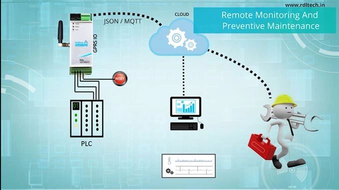
Automated Machine Fault Alerting System


The prime functionality of alerting system is monitoring and quick detection of issues. Downtime is one of the dreaded terms and it occurs when the system is subjected to partial or full loss of availability thereby resulting in a loss. Loss could be in any form, revenue, time, output.
A comprehensive monitoring system that allows timely identification of issues proves to be indispensable. Also, it is important that a monitoring system allows operators to drill down from high level to granular level information so that those specific points can be used for root cause analysis
  1. Step 1 , Copy the code and configure the parameter as required by you 


Step 2 - Execute the code

sample SMS Alert Code for your Reference
  
/*
Pin Mapping :
* PLC output1 ---------> Indino IN0
* PLC output2 ---------> Indino IN1
* PLC output3 ---------> Indino IN2
* PLC output4 ---------> Indino IN3
*/
#include <IndinoDI.h>  
char number[]= "94xxxxxxxx"; //Number to which message to be sent
char message1[]= "Zone 1 temperature is High,required attention"; //Alert Message1
char message2[]= "Pressure level dropped below the average,need attention"; //Alert Message2
char message3[]= "Oil level low,need attention "; //Alert Message3
char flag1=0;
char flag2=0;
char flag3=0;
const int SensorPin_1= 33; //The number of the Sensor pin 1
const int SensorPin_2= 34; //The number of the Sensor pin 2
const int SensorPin_3= 35; //The number of the Sensor pin 3
const int ResetPin= 32; //The number of the ResetPin  
void setup()
{  
/*   initialisation IO as an input:     */
pinMode(SensorPin_1,INPUT); 
pinMode(SensorPin_2,INPUT); 
pinMode(SensorPin_3,INPUT); 
pinMode(ResetPin,INPUT); 
Serial.begin(9600);
}
void loop()
{
if (digitalRead(SensorPin_1)==HIGH) //Check for alert input high
{
if(flag1==0) //Send the message only if flag is reset
{
Indino_GSM_Send_SMS(number, message1); //Command to send SMS
Serial.print(message1);
flag1=1; //Flag set to send the message  
delay(5000); //Delay call 5sec to send message only once
}
}
if (digitalRead(SensorPin_2)==HIGH) sample SMS Alert Code for your Reference
{
if(flag2==0) 
{
Indino_GSM_Send_SMS(number, message2); 
Serial.print(message2);
flag2=1;
delay(5000);
}
}
if (digitalRead(SensorPin_3)==HIGH)
{  
if(flag3==0)
{
Indino_GSM_Send_SMS(number, message3);
Serial.print(message3);
flag3=1;
delay(5000);
}
}
if (digitalRead(ResetPin)==HIGH) //Check for Reset to reset the device
{
flag1=0;  
flag2=0;  
flag3=0; 
}
}