Pages

Friday, 16 October 2015

Automatic Meter Reading DIY KIT

OVERVIEW:

Automatic meter reading, or AMR, is the technology of automatically collecting consumption, diagnostic, and status data from energy metering devices (electric) and transferring that data to a central database for billing, troubleshooting, and analyzing. This technology mainly saves utility providers the expense of periodic trips to each physical location to read a meter. Another advantage is that billing can be based on near real-time consumption rather than on estimates based on past or predicted consumption. 

WORKING:

From the above block diagram, 
To achieve the instrument of data copying and transmission and other functions GPRS module is used. GPRS is networks for remote communication. They can combine with each other, through the net work’s gateway to achieve a user meter copying to control and transfer in distance.
Automatic Meter Reading system should have the following functions:
  • Timing, location, automatically copies the user's Electricity volume.
  • Low-power, low cost, reliable, safe.
  • To realize the transmission and processing of data in distance.
  • Through internet, updating meter readings and faults to real time data base.
  • Later Data analysis is carried out to present billing information of individual meter reading systems. 
  • Buzzer is turned ON to indicate “ Due bills ” 
  • LCD is provided to display current meter readings and energy consumption.
  • Also billing information will be sent through SMS as well. 

COMPONENTS REQUIRED:

  • ATMEGA UNO 328.
  • Two Relay shields
  • GPRS Shield
  • Jumper wires
  • Screw shield.
  • Buzzer
  • LCD Shield.


Thursday, 15 October 2015

ANDROID CONTROLLED BOT DIY KIT

OVERVIEW:


The DIY KIT works on the concept of Bluetooth android remote control application, these command so received from any android phone can control robot movement.
As per the commands sent from the sender’s mobile, the microcontroller will send signals the movement of the robot.

WORKING:

From the above block diagram,
Robot is controlled by a android mobile phone with remote control application installed. Initially both the Bluetooth devices should be paired.
If any button is pressed a byte corresponding to the button presses is heard at the other end of the Bluetooth receiver. The microcontroller is programmed to take appropriate movement action for a given input. These decisions will be used to driver the motors forward, backward, left and right via l298 motor driver.

COMPONENTS REQUIRED:

  • Bluetooth module.
  • BOT. 
  • Jumper wires.
  • 12 DC power supply.

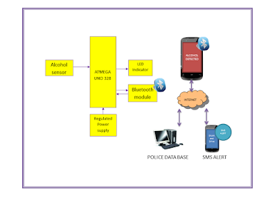
Alcohol Detection Smart android DIY KIT


OVERVIEW:

In recent years, it has become a fantasy that the people put their lives in risk. More often, the people consume alcoholic drinks and drive the vehicles. There are more chances that the person can hit the vehicle to any obstacle approaching him in the opposite direction due to unconsciousness caused by drinking. Hence, we make a modest attempt to design and develop a simple, low cost alcohol detection android application using an independent microcontroller.
The main aim of this project is to design a system that can identify whether the person, driving the vehicle, is in complete conscious state or not. The designed and developed system is installed in the module confining microcontroller, alcohol sensor and Bluetooth module.


WORKING:

From the above block diagram,
If the driver is drunk, the alcohol sensor fixed to the microcontroller will identify the alcohol content and its output will be triggered. This output of the sensor will be sent as an input to the microcontroller. Thus, the microcontroller continuously sends real time sensed alcohol detected values to the Bluetooth application where police is using at the scene, now android application analyses the streaming sensor values and display the level of alcohol detected.
If the alcohol level is above the normal range then it displays the detected level along with corresponding violated due amount and also sends those information to the police data base and in turn violation due amount will be placed via SMS to the driver.

COMPONENTS REQUIRED:

  • ATMEGA UNO 328.
  • Bluetooth shield
  • Alcohol sensor.
  • Jumper wires
  • Screw shield.
  • Android application

Friday, 9 October 2015

RFID Reader-TTL


OVERVIEW:

This is a low frequency (125Khz) RFID Reader With TTL Output with range upto 15cms. The RFID Reader  is designed specifically for low-frequency (125 kHz) passive tags.Frequency refers to the size of the radio waves used to communicate between the RFID system components.

RFID Reader - TTL Features:


  • Low-cost method for reading passive RFID tags.
  • Built in Antenna
  • On-Board Power LED
  • Current Requirement <120mA
  • Communication TTL at 9600 baud.
  • Detecting Range upto 0-15cms.
  • High quality PCB FR4 Grade with FPT Certified. 
RFID Reader - TTL  Applicatons:
  • Rfid based attendance system
  • Rfid based smart shopping system 
  • Rfid based medical file tracking system 
  • Rfid based inventory management system
  • Rfid based access control system -security 
  • Rfid based library management system 
  • Rfid based security guard monitoring system
  • Rfid based asset tracking system ,
  • Rfid based vehicle parking system
  • Rfid based toll gate collection system
  • Rfid hotel room access control system .
  • Rfid based product identification for blind
  • Rfid based blind indoor navigation system.
  • Rfid based dual authentication system for software application ,
  • Rfid based industry supply chain control system
  • Rfid based smart conveyor
FOR MORE SCHEMATIC AND SAMPLES CODES: CLICK HERE


Thursday, 8 October 2015

Bread Board Power Supply

OVERVIEW:

The breadboard power supply kit that takes power from a DC adapter jack  and provide outputs a selectable 1.8V,3.3V,5V,9V,12V and custom adjustable voltage from 0V to 12V.  Breadboard power supply headers are mounted on the bottom of the PCB for simple insertion into a breadboard.


PRODUCT FEATURES:


  • 1.8V,3.3V,5V,9V,12V regulated voltage.
  • Dual lane output.
  • Dual power port input.
  • Custom linear adjustable voltage from 0V to 12V.
  • Dual regulated power supply.
  • USB option for connecting Raspberry Pi and USB driven board 5V up to 1A.
  • Special designed for Breadboard usage.
For More Information: CLICK HERE


Saturday, 5 September 2015

Smart Home Using Matlab GUI


OVERVIEW:

The popularity of home automation has been increasing greatly in recent years due to much higher affordability and simplicity through smartphone and computer connectivity. Home automation may include centralized control of lighting, HVAC (heating, ventilation and air conditioning), appliances, security locks of gates and doors and other systems, to provide improved convenience, comfort, energy efficiency and security. 


 Smart Home Using Matlab GUI Block Diagram:


Smart Home Using Matlab GUI Working Principle:


The microcontroller/processor is used to monitor and control the devices. An embedded c program is pre written into the microcontroller/processor which is programmed according to our need. The microcontroller/processor is then interfaced with the relays and the necessary water level sensors. Matlab will send a serial data to the microcontroller/processor via the serial interface.The microcontroller/processor replies if necessary and does the task assigned to it. The part of Matlab GUI is solely to provide user interface which when interrupted sends data to microcontroller/processor.

For More Details:


Controller:


  • Atmel (8051/89c52)/ PIC

Smart Home Using Matlab GUI Software Requirements:


  • MATLAB 2008 and above
  • LANGUAGE-Embedded C.
  • TOOLS: mikroC PRO for PIC/KEIL

Smart Home Using Matlab GUI Kits Contains:


  • PCB and programmed Microcontroller/Processor
  • Water Level Sensors (3)
  • 4 Relay Board
  • 1 Relay Board
  • USB to TTL converter
  • transformer (12 volts)
  • CD/DVD Project Report &CBT(Computer Based Training)*
  • Source code and datasheets
Reference :

Above design based on latest IEEE, Spring and other  international journal and Publication .The reference paper will be given along with kits.

Smart Home Using Matlab GUI Kits Details:

PIC Controller  

4 Relay  


Miscellaneous.

Friday, 4 September 2015

LAN Based RFID Reader

OVERVIEW:

Ethernet RFID Reader is based on TCP/IP, can read RFID cards.This readers can easily connect to network.Installation is very easy. 


RFID Reader Features:


  • Low-cost method for reading passive RFID tags.
  • Built in Antenna
  • On-Board Power LED
  • Current Requirement <120mA
  • Detecting Range 5-15cms.
  • High quality PCB FR4 Grade with FPT Certified. 

RFID Reader - Applicatons:

  • RFID Remote/Web based attendance system
  • RFID Remote/Web based smart shopping system 
  • RFID Remote/Web based medical file tracking system 
  • RFID Remote/Web based inventory management system
  • RFID Remote/Web based access control system -security 
  • RFID Remote/Web based library management system 
  • RFID Remote/Web based security guard monitoring system
  • RFID Remote/Web based asset tracking system ,
  • RFID Remote/Web based vehicle parking system
  • RFID Remote/Web based toll gate collection system
  • RFID Remote/Web based hotel room access control system .
  • RFID Remote/Web based product identification for blind
  • RFID Remote/Web based blind indoor navigation system.
  • RFID Remote/Web based dual authentication system for software application ,
  • RFID Remote/Web based industry supply chain control system
  • RFID Remote/Web based smart conveyor

Ethernet Shield W5100 for Arduino:


  • With this Ethernet Shield, your Arduino board can be used to connect to internet.
  • Can be used as server or client.
  • Directly plug puzzle board, no soldering required.
  • Controller: W5100.
  • This is the latest version of the Ethernet Shield.
  • This Arduino Ethernet Shield which is based on the Wiznet W5100 Ethernet Chip gives you an easy way to get your Arduino Online.
  • It is directly supported by Arduino official Ethernet Library.
  • It adds a micro-SD card slot, which can be used to store files for serving over the network.
  • It is compatible with the Arduino Duemilanove (168 or 328), Uno as well as Mega (1280/2560) and can be accessed using the SD library.
  • The Wiznet W5100 provides a network (IP) stack capable of both TCP and UDP.
  • It supports up to four simultaneous socket connections.
  • Use the Ethernet library to write sketches which connect to the internet using the shield.
  • Fits all version of Arduino Main board,2009,UNO, mega 1280, mega 2560.
  • Size: 7cm x 5.4cm x 2.4cm - 2.76inch x 2.12inch x 0.94inch.
  • MAC address: 0xDE, 0xAD, 0xBE, 0xEF, 0xFE, 0xED byte mac[] = { 0xDE, 0xAD, 0xBE, 0xEF, 0xFE, 0xED }
Mega 2560 R3 ATmega2560-16AU Board Features:


  • Microcontroller:ATmega2560
  • Operating Voltage: 5V
  • Input Voltage (recommended):7-12V
  • Input Voltage (limits):6-20V
  • Digital I/O Pins: 54 (of which 14 provide PWM output)
  • Analog Input Pins:16
  • DC Current per I/O Pin:40 mA
  • DC Current for 3.3V Pin: 50 mA
  • Flash Memory:256 KB of which 4 KB used by bootloader
  • SRAM:8 KB
  • EEPROM:4 KB

LAN Based RFID Reader Block Diagram:


LAN Based RFID Reader Connection Diagram:


LAN Based RFID Reader Screenshot:


LAN Based RFID Reader Sample SDK Screenshot:


LAN Based RFID Reader Sample C# SDK Screenshot:


For More codes and software: Click Here