Pages

Thursday, 21 August 2014

Joystick Shield with XBEE


Quick Overview
The Joystick Shield easily stacks on top of your ATmega 328 R3 and turns it into a simple robotic and gaming controller. Six momentary push buttons (4+2), a two-axis thumb joystick and optional remote transmission adapter for Xbee and Bluetooth allows your ATmega 328 R3 to control from remote location.


Features : 
  • Jumbo yellow 4 keypad.
  • Joystick.
  • Two selection switch.
  • With xbee.
  • Compatible with UNO R3 and Mega 2560.
For More Details Please CLICK HERE


FT232 BreakOut Board


Quick Overview
It’s a common high speed IC used to convert USB to serial converter. It’s quite commonly used to connect a microcontroller TTL data to any USB interface host to establish a bridge for communications between USB to serial devices. This particular breakthrough board can be used to program RDL UNO ATMEGA 328 and use directly in to your own circuits. Also this breakthrough board can also act as a bridge between Xbee and its Xbee utility software to configure various Xbee’s.
Features : 
  • Simple and convenient design for the hobbyist and developers.
  • High speed bridge converting USB to Serial, serial to USB


For More Details Please CLICK HERE


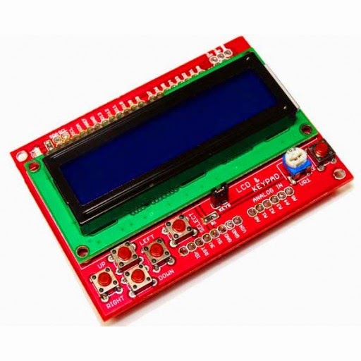
LCD KEYPAD Shield


Quick Overview
One of the basic interfacing requirements for the hobbyists or electronics enthusiasts is I/P (keypad) and O/P (LCD display)  for proyotype applications. This shield uses minimum number I/O’s that is 4 bits for LCD data and 2 control signal lines for the same. A single analog pin (Pin A0) is multiplexed to read 5 input key switches (Navigation keys). Each key has been pulled up to a different voltage level, so a different voltage will be generated every time a user selects a key. This voltage could be read by the analog pin A0 on the board. Hence saves the no of I/O pins.  The backlight of the LCD could be controlled by setting PWM (Pin D10) by adding a few lines of code


Features :
  • 16X2 Blue color back light LCD.
  • A single Analog pin is multiplexed to read 5 input Keys.
  • Optional PWM based Back light control.
  • Stackable on UNO shield

For More Details Please CLICK HERE

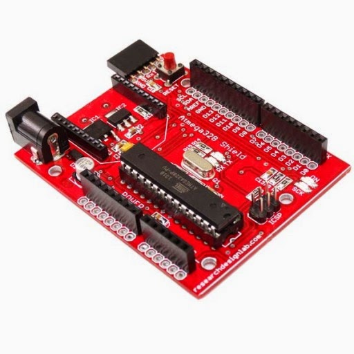
UNO ATMEGA328 Development Board - Programmed with Arduino


Quick Overview
Atmega 328 is one of the most commonly used Micro controllers with open source platform amongst many hobbyist and industrial communities. The simplicity and the low power of Atmega 328 helps design many prototype boards which could be used in numerous applications.We introduced RDL UNO Atmega 328 development board having common UNO interface to the available shields. The board also has inbuilt Xbee footprint with memory card interface in a single compact board without the need of doing external connections and hence as a whole the final product becomes cost effective. The RDL UNO Atmega 328 also includes 6 analog inputs, 14 digital I/O pins (6 amongst these could be used as PWM outputs), a crystal oscillator with 16MHz frequency, a 5 pin female connector to connect FT232 plugin, a power jack, a reset button and an ICSP header. This board does not have an inbuilt USB to directly load the program from the computer. As we all know, once the program has been dumped into the board, the part of the USB connectors become useless. So to load the program we have given common interface through FT232 breakthrough board where we can connect to a computer and load the codes into the RDL UNO Atmega 328. Since the USB interface has been removed, we have provided Xbee foot print and Micro SD card slot which is commonly used by many electronics enthusiasts. Once the program has been dumped into the RDL UNO Atmega 328 we can remove the FT232 plugin and could be used independently for other purposes.This board is fully compatible with Arduino like open source software.


RDL- UNO ATMEGA328 Development Board - Programmed with Arduino


Features : 
  • Atmega328p- controller
  • Standard I/O interface for UNO shield.
  • Xbee foot print for RF/WiFi communication.
  • Inbuilt Micro SD memory card slot for Data logging application.
  • Programmable with Arduino open source.
For More details Please CLICK HERE


Monday, 30 June 2014

Xbee Development Board with Voltage Regulator and Level Converter Compatible for Arduino

Quick Overview

Arduino Xbee Adapter Development Board allows an Arduino board to communicate wirelessly using  Zigbee or BlueTooth.This shield is build up by two parts: Bluetooth and Xbee shield.This Bluetooth shield is a serial port Bluetooth module (Slave/Master) breakout board. you can directly stack on Arduino and use the UART port for Bluetooth communication.XBee Shield is an enhanced Zigbee XBee Series modules breakout board for Arduino, it can directly plug in with Arduino, and use any pin of the basic board to connect with the XBee module serial port.XBee Shield with Logic Level Converter is an enhanced serial port XBee module breakout board.It can directly plug in with Arduino.


 Xbee Development Board with Voltage Regulator and Level Converter Compatible for Arduino


Features:
  • Compatible with all Arduinos.
  • Can be use as XBEE development board.
  • Mounts directly onto your Arduinos.
  • Reset button brought out.
  • With Logic Level Converter (3.3V to 5V ).
  • Stackable interfaces.
For more details please Click Here

Xbee USB Adapter with FT232RL

Quick Overview

Xbee USB Adapter with FT232RL  shield works with all XBee modules including the Series 1 and Series 2.5, standard and Pro version.Plug the unit into the XBee shield, attach a mini USB cable, and you will have direct access to the serial and programming pins on the XBee unit.

Xbee USB Adapter with FT232RL

Features:
  • 3.3V and 5V dual power output
  • 3.3V and 5V IO compatible
  • USB 2.0 protocol
  • Needs no external crystal
  • UART interface support for 7 or 8 data bits, 1 or 2 stop bits and odd / even / mark / space / no parity
  • Power Supply USB 5V.
  • Single chip USB to asynchronous serial data transfer interface.
  • Data transfer rates from 300 baud to 3 Mbaud (RS422, RS485, RS232 ) at TTL levels.
  • UART interface support for 7 or 8 data bits, 1 or 2 stop bits and odd / even / mark / space / no parity.
  • Integrated +3.3V level converter for USB I/O.
  • True 5V/3.3V/2.8V/1.8V CMOS drive output and TTL input.

Driver Tutorial

 For Download Click Here

For more Please Click Here


L298N Motor Drive Shield

Quick Overview

L298N is a high voltage, high current motor driver chip, with the highest working voltage of 46V, continuous operating current of 2A, and instantaneous peak current up to 3A. The chip contains two "H bridges" which are high-voltage and high current full-bridge drivers that can directly drive two DC motors.

L298N Motor Drive Shield  


Features:
  • Driver: L298N Dual H Bridge DC Motor Driver IC
  • Motor Power Supply Vs: +5 V to +35 V
  • Max average current 2A
  • peak current Io: 3A
  • Logic Level Power Vss: +5 V ~ +7 V (Onboard 5V Regulator can be used if Motor Power is > 7.0V)
  • Logic level power: 0 ~ 36mA
  • Two motor direction indicator LEDs.
  • Screw-terminals for power and motor connections.
Sample codes:
//Program 1: PWM Speed Control 
int E1 = 9; 
int M1 = 4; 
int E2 = 10; 
int M2 = 5; 
 
void setup() 
 pinMode(M1, OUTPUT); 
 pinMode(M2, OUTPUT); 
 
void loop() 
 int value; 
 for(value = 0 ; value <= 255; value+=5) 
 { 
 digitalWrite(M1,HIGH); 
 digitalWrite(M2, HIGH); 
 analogWrite(E1, value); //PWM Speed Control 
 analogWrite(E2, value); //PWM Speed Control 
 delay(100); 
 } 
 
//Program 2: Motor Direction control
int ENA=9; //Connect on Pin 9
int IN1=4; //Connect on Pin 4
int IN2=5; //Connect on  Pin 5
int ENB=10; //Connect on Pin 10
int IN3=6; //Connect on  Pin 6
int IN4=7; //Connect on  Pin 7
 
void setup() {
 pinMode(ENA,OUTPUT);
 pinMode(ENB,OUTPUT);
 pinMode(IN1,OUTPUT);
 pinMode(IN2,OUTPUT);
 pinMode(IN3,OUTPUT);
 pinMode(IN4,OUTPUT);
 digitalWrite(ENA,HIGH);// Activate motor A
 digitalWrite(ENB,HIGH);// Activatemotor B
}
void loop(){
 
 digitalWrite(IN1,LOW);
 digitalWrite(IN2,HIGH);
 digitalWrite(IN3,HIGH);
 digitalWrite(IN4,LOW);
 delay(1000);
 digitalWrite(IN1,LOW);
 digitalWrite(IN2,HIGH);
 digitalWrite(IN3,LOW);
 digitalWrite(IN4,HIGH);
 delay(1000);
 digitalWrite(IN1,HIGH);
 digitalWrite(IN2,LOW);
 digitalWrite(IN3,LOW);
 digitalWrite(IN4,HIGH);
 delay(1000);
 digitalWrite(IN1,HIGH);
 digitalWrite(IN2,LOW);
 digitalWrite(IN3,HIGH);
 digitalWrite(IN4,LOW);
 delay(1000);
}

For more details Click Here