Pages

Sunday, 17 November 2013

Fire Sensor

Overview


     The Fire sensor, as the name suggests, is used as a simple and compact device for protection against fire. The module makes use of IR sensor and comparator to detect fire up to a range of 1 - 2 meters depending on fire density.
 
Fire Sensor:


Features

  • Allows your robot to detect flames from 2m away. 
  • Fire indicator led. 
  •  Calibration preset for range adjustment.

 Application

  • Industrial heating and drying systems 
  •  Domestic heating systems 
  •  Industrial gas turbines
Using The Sensor
·         Connect ground and vcc pin to +5v and gnd.
·         Connect out pin to port pin of controller for interfacing with applications.

Working
      The fire sensor circuit is too sensitive and can detect a rise in temperature of 10 degree or more in its vicinity. Ordinary signal diodes like IN 34 and OA 71 exhibits this property and the internal resistance of these devices will decrease when temperature rises. In the reverse biased mode, this effect will be more significant. Typically the diode can generate around 600 milli volts at 5 degree centigrade. For each degree rise in temperature; the diode generates 2 mV output voltage. That is at 5 degree it is 10 mV and when the temperature rises to 50 degree, the diode will give 100 milli volts. This voltage is used to trigger the remaining circuit. Transistor T1 is a temperature controlled switch and its base voltage depends on the voltage from the diode and from VR and R1. Normally T1 conducts (due to the voltage set by VR) and LED glows. This indicates normal temperature.


ARM Schematic:
ARM Code:
For Arm Code Click Here

ATMEL Schematic:
ATMEL Code:
For ATMEL Code Click Here

PIC Schematic:

PIC Code:
For Pic Code Click Here.


Saturday, 16 November 2013

Digital Light Intensity Sensor

Overview


Light Intensity sensor  also known  as photoconductor  or photocell,  is a  device which has a resistance  which  varies according to the amount of light  falling on its  surface. Since  LDR  is  extremely  sensitive  in  visible  light  range,  it  is  well  suited  for  any  application.

Digital Light Intensity Sensor


Features

  • Wide spectral response 
  •  Low cost 
  •  Wide ambient temperature range
Applications

  • Ambient light sensing 
  •  Proximity sensing
Using The Sensor

  • Connect +5v to pin 2 and ground to pin 5 and 6. 
  •  Pin 4 and 5 should be connected to particular transmitter and receiver pin of controller. 
  •  Output pin may be connected to any port pins and can be used to any application.
Working
An  LDR  and  a  normal  resistor  are  wired  in  series  across  a  voltage,  as  shown  in  the circuit  below.  Depending  on  which  is tied to the  5V  and  which  to 0V, the  voltage  at  the  point  between  them,  call  it  the  sensor  node,  will  either  rise  or  fall  with  increasing  light.  If  the  LDR  is  the  component  tied  directly  to  the  5V,  the  sensor  node  will  increase in voltage with increasing light  The  LDR's  resistance  can  reach  10  k  ohms  in  dark  conditions  and  about  100  ohms  in full brightness.  The  circuit  used  for  sensing  light  in  our  system  uses  a  10  kΩ  fixed  resistor  which  is tied  to +5V. Hence the voltage value in this case decreases with increase in light intensity. The  sensor  node  voltage  is  compared  with  the  threshold  voltages  for  different  levels of light intensity corresponding to the four conditions Optimum, dim, dark and night. The  relationship between the resistance RL and light intensity Lux for a    typical LDR is:
                                               RL  = 500 / Lux kΩ    …(3.1)
   With the LDR connected to 5V through a 10K resistor, the output voltage of the DR is:                                      
                                                              Vo = 5*RL  / (RL+10)        … (3.2)
In order to increase the sensitivity of the sensor we must reduce the value of the fixed resistor in series with the sensor. This may be done by putting other resistors in parallel with it.


 Pin Out Details:


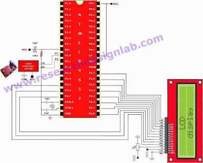
ATMEL DIGITAL IO Schematic:
ATMEL DIGITAL IO Code:
 For Code Please Click Here

ATMEL UART Schematic:


ATMEL UART Code:
For Code Click Here.