Pages

Thursday, 14 November 2013

LCD INTERFACING Module

Overview
LCD stands for Liquid Crystal Display. LCD is finding wide spread use replacing LEDs (seven segment LEDs or other multi segment LEDs) because of the the ability to display numbers, characters and graphics. This is in contrast to LEDs, which are limited to numbers and a few characters.

LCD INTERFACING MODULE:


Features :
  • Can display 224 different symbols.
  •  Low power consumption. 
  • Powerful command set and user-produced characters
  • 5 x 7 dot matrix format.

ARM SCHEMATIC:
ARM CODE:
FOR LCD INTERFACING ARM CODE CLICK HERE

ATMEL SCHEMATIC:

ATMEL CODE:
FOR LCD INTERFACING ATMEL CODE CLICK HERE

PIC SCHEMATIC:
PIC CODE:
FOR PIC CODE CLICK HERE


Digital Dimmer Module

Overview 
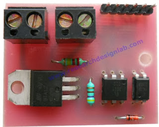
The board can be used in applications where dimming of 110-220V AC power is required like dimming of bulb or fan. The input can be simple 4 bit high/low signal from microcontroller working at 3V or 5V which is isolated with the use of opto-couplers. Total of 16 levels of power control can be set from totally off(0%) to full on(100%) as per input control levels.

Digital Dimmer Module:
www.researchdesignlab.com


 Features:

  • Works on AC power supply
  • Load Capacity 12 Amp AC
  • Isolated Input 3-5V DC
  • Works from any microcontroller input
  • 16 Levels of Control


PIN Out Details:
SCREEN SHOTS:


Input for Dimmer module:
Input for Dimmer module is of digital input of 4bit data.D0, D1, D2, D3 are the input pins of dimmer which can be connected to I/O pins microcontroller. 16 level of dimmer controlling input of 0 to 100% is shown below.
For INPUT DETAILS please CLICK HERE


ATMEL Schematic:


ATMEL CODE:
FOR ATMEL CODE CLICK HERE

PIC SCHEMATIC:
PIC CODE:
FOR PIC CODE CLICK HERE